ALLPCB


Flexible printed circuit boards enable compact, reliable interconnections in automated systems where space constraints and movement demand more than traditional rigid boards can provide. In industrial automation, these circuits support dynamic applications such as robotic arms, conveyor controls, and sensor networks that must operate continuously under vibration, temperature swings, and mechanical flexing. Engineers select flexible PCBs when designs require repeated bending or three-dimensional routing that rigid boards cannot accommodate without additional connectors or wiring harnesses. This capability reduces assembly complexity while improving signal integrity in control systems.
Why Flexible PCBs Matter in Industrial Automation
Flexible PCBs address key limitations of rigid boards in environments that involve motion or irregular geometries. They allow circuits to conform to curved surfaces or fold into tight enclosures common in automated machinery. This adaptability supports higher component density and shorter signal paths, which help maintain performance in high-speed data transmission for industrial control systems. Procurement teams and designers often evaluate flexible options when equipment must withstand repeated flex cycles without fatigue failures. The result is more reliable operation in applications ranging from packaging lines to precision assembly robots.
Technical Principles of Flexible PCB Construction
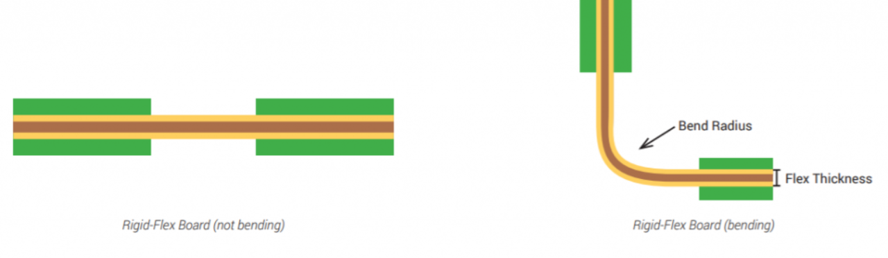
Flexible PCBs rely on thin, bendable dielectric substrates such as polyimide films that maintain electrical performance while permitting mechanical movement. Conductive copper traces are etched onto these substrates, with coverlays or coatings protecting the circuitry from environmental exposure. In rigid-flex constructions, rigid sections provide mounting areas for components while flexible sections handle interconnections between modules. Engineers follow established design rules for bend radius and trace layout to prevent stress concentrations that could lead to cracking during operation. Thermal expansion differences between materials require careful stack-up planning to avoid delamination under temperature cycling typical in factory settings.
Designing Flexible PCBs for Harsh Industrial Environments
Designers begin by defining the expected flex life, temperature range, and chemical exposure for the target application. Trace widths and spacing follow guidelines that account for dynamic flexing rather than static conditions alone. Ground planes and shielding layers are incorporated where electromagnetic interference from nearby motors or drives could affect signal quality. Material selection emphasizes low moisture absorption and high thermal stability to ensure long-term reliability. Simulation tools help predict mechanical stress before prototyping, allowing adjustments that align with performance specifications for industrial equipment.
Rigid-Flex PCBs in Industrial Automation Systems
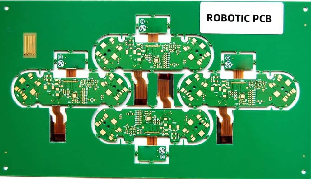
Rigid-flex PCBs combine the mechanical stability of rigid sections with the flexibility of interconnects in a single assembly. This hybrid approach eliminates separate connectors that can become failure points under vibration common in automated production lines. In control cabinets or on moving platforms, the rigid areas support heavy components while flexible zones route signals around obstacles. Assembly processes must account for the transition zones between rigid and flexible sections to maintain planarity during soldering. Such constructions prove especially useful in multi-axis robotic systems where space and weight savings directly influence overall equipment efficiency.
Flexible PCB Assembly for Industrial Control Systems
Assembly of flexible PCBs requires specialized handling to prevent damage during component placement and reflow. Stencils and fixtures are adapted to accommodate the thin, pliable nature of the boards. Surface-mount components are attached using processes that control heat exposure to avoid warping the substrate. Through-hole components, when used, demand careful lead forming to maintain flexibility in designated areas. Post-assembly testing includes continuity checks and flex cycling to verify that connections remain intact after repeated movement. These steps help ensure the finished assemblies meet the demands of continuous industrial operation.
Best Practices for Reliable Performance
Engineers apply strain relief features such as gradual transitions in trace direction and reinforced bend areas to extend service life. Coverlay openings are minimized around high-stress zones, and adhesive selection matches the expected environmental conditions. Documentation of flex cycle requirements guides both design and qualification testing. Collaboration between design and manufacturing teams early in the project helps identify potential issues with material compatibility or assembly tolerances. Following these practices supports consistent quality across production volumes for automation equipment.

Conclusion
Flexible and rigid-flex PCBs provide essential solutions for the spatial and mechanical challenges inherent in modern industrial automation. Their ability to integrate reliable circuitry into dynamic environments supports more compact and efficient machine designs. By applying sound engineering principles and established qualification methods, teams can achieve dependable performance that aligns with the operational demands of automated systems. Continued attention to material properties and assembly techniques will remain important as automation complexity increases.
FAQs
Q1: What are the main flexible PCB applications in automation?
A1: Flexible PCBs find use in robotic joints, sensor arrays on moving conveyors, and compact control modules where traditional wiring would add bulk or failure points. They enable three-dimensional routing and repeated flexing while preserving signal integrity in industrial environments. Designers select them when equipment geometry or motion profiles exceed the capabilities of rigid boards.
Q2: How do flexible PCBs improve benefits of flexible PCBs in industrial equipment?
A2: They reduce connector count, lower overall assembly weight, and allow circuits to conform to available space inside machinery. This leads to fewer potential failure points and improved vibration resistance in continuous-operation settings. The result is often higher reliability and simplified maintenance for automated production systems.
Q3: What considerations guide designing flexible PCBs for harsh environments?
A3: Key factors include selecting substrates with appropriate thermal and chemical resistance, defining realistic bend radii, and incorporating protective coatings against moisture or contaminants. Engineers also plan for thermal expansion mismatches and perform cycle testing to confirm durability under expected factory conditions.
Q4: How do rigid-flex PCBs support industrial control systems?
A4: Rigid-flex constructions provide stable mounting areas for processors and connectors while using flexible sections for interconnections that must move or fold. This integration simplifies assembly and enhances reliability in vibration-prone automation equipment by eliminating separate cables between modules.
References
IPC-6013D — Qualification and Performance Specification for Flexible/Rigid-Flexible Printed Boards. IPC, 2023
IPC-2223D — Sectional Design Standard for Flexible/Rigid-Flexible Printed Boards. IPC, 2023
IPC-A-600K — Acceptability of Printed Boards. IPC, 2020
ISO 9001:2015 — Quality Management Systems. ISO, 2015