 ALLPCB


1. Overview
System watchdog timers are commonly used in embedded systems to help prevent software faults, system lockups, tampering, and unintended behavior, supporting system health and safety.
In the AMD Versal adaptive SoC, a SWDT is integrated in each of the FPD (full power domain) and LPD (low power domain) to support system development. The overall block diagram is shown below:
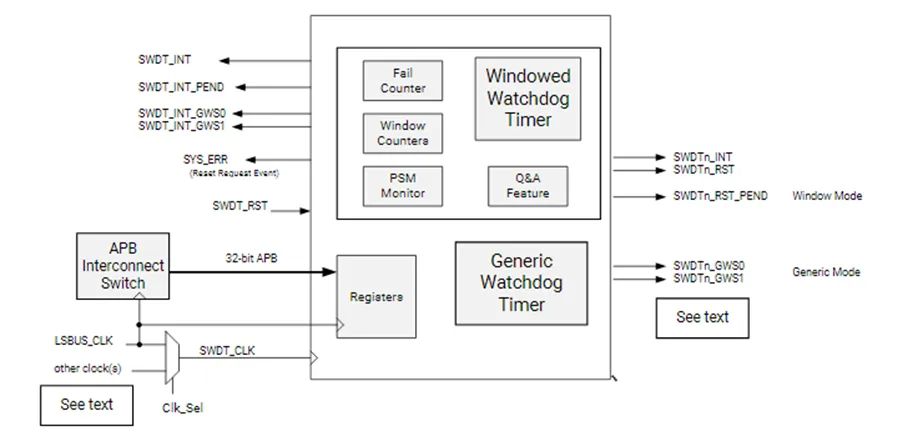
The block diagram shows two different watchdog timer types inside SWDT: the windowed watchdog timer and the generic watchdog timer.
Before using the SWDT, confirm that the system-level resets for LPD and FPD have been released, for example the CRL.RST_LPD_SWDT register and the CRF.RST_FPD_SWDT register.
2. Generic Watchdog Timer
The generic timer mode involves three registers: G_Refresh, G_Offset, and G_CSR.
G_CSR enables the generic timer mode and provides status feedback.
G_Offset configures the timer period.
G_Refresh is used to refresh the timer, i.e. to feed the watchdog.
The operation is illustrated below:
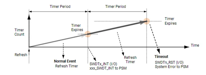
In generic mode there can be up to two timer periods. When the counter reaches the first period, the timer generates a timer interrupt. The counter then continues; when it reaches the second period, the timer generates a timeout interrupt. Before the counter reaches the second period, software can refresh the counter via the G_Refresh register to restart timing.
The generic mode is simple to use. Note, however, that when a timeout occurs in generic mode, it does not output a system-level error to the PSM error stack and therefore will not generate a system error that triggers system-level actions in PSM or PLM firmware.
3. Windowed Watchdog Timer
The windowed mode provides a more comprehensive set of functions that consider a variety of system security scenarios.
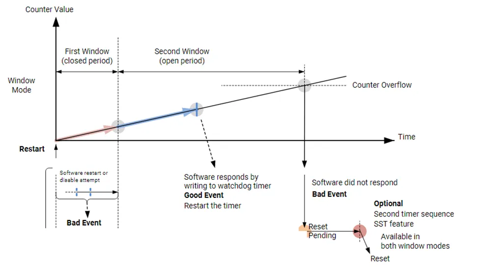
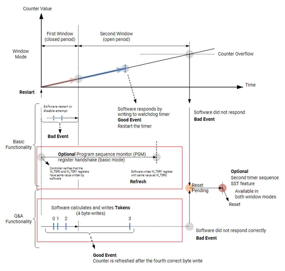
The basic windowed workflow can be divided into three parts: the First Window, the Second Window, and the Second Sequence Timer. Five registers are involved: Enable_and_Status, Funct_Ctrl, First_Wind, Second_Wind, and SST_COUNT.
The first window is a closed interval during which the application must not refresh or reset the watchdog. If a refresh or reset is attempted during this interval, an error event occurs and a system error is reported to PSM and PMC. This protects the watchdog from inappropriate operations.
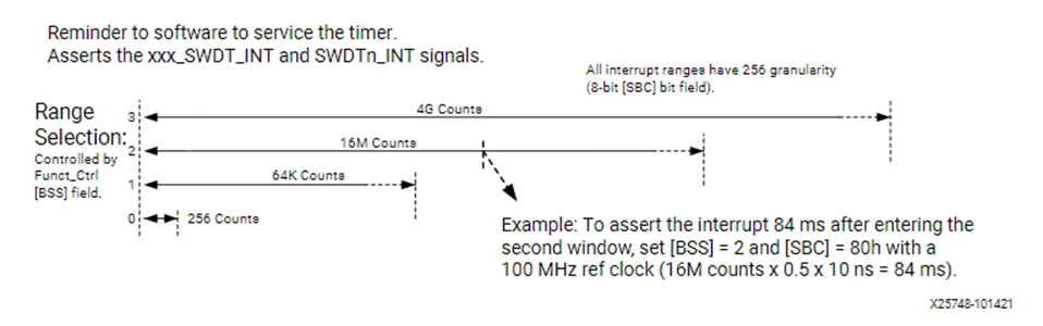
When the first window expires, the watchdog generates an interrupt to notify the system. The interrupt timing can be configured via the BSS and SBC bits in the Funct_Ctrl register. After receiving the interrupt the application can refresh the watchdog or reset/stop/reconfigure it.
If the application does not take any action during the second window and the timer exceeds the configured second window time, a timeout interrupt occurs. If the Second Sequence Timer is enabled, the watchdog will not immediately generate a system error; instead it waits until the second sequence timer completes before producing the system error. This delay gives the application time to record state, logs, or to perform device handling useful for debugging or improving safety. If the second sequence timer is not configured, the watchdog will immediately generate an error event and send a system error to PSM and PMC once the second window times out.
In summary, the application may only refresh the watchdog or perform reset/stop/reconfigure operations during the second window; otherwise an error event is generated and reported to PSM and PMC. Additional points:
- The first window time can be set to 0 to skip the protection period.
- If the entire watchdog is reset via system-level resets for LPD and FPD during any window, no extra interrupt or system error is generated.
To further enhance safety, the windowed mode provides two advanced anti-abuse features: the signature method (PSM) and the question-and-answer method (Q&A), highlighted in the image below.
1. Signature Method (PSM)
Before starting watchdog timing, the user must store a signature in the Task_Sig0 register. Before refreshing the watchdog during the second window, the application must write the same signature into the Task_Sig1 register. When a normal refresh occurs, the watchdog compares these two signatures; if they differ, an error event is immediately generated and a system error is output to PSM and PMC.
2. Question-and-Answer Method (Q&A)
Before running the watchdog, the user sets a seed and feedback value in the Token_fb register. These values, together with the ACNT bit in the Enable_and_Status register, are used to compute the value written into the Token_Resp register. The algorithm is shown in the table below.
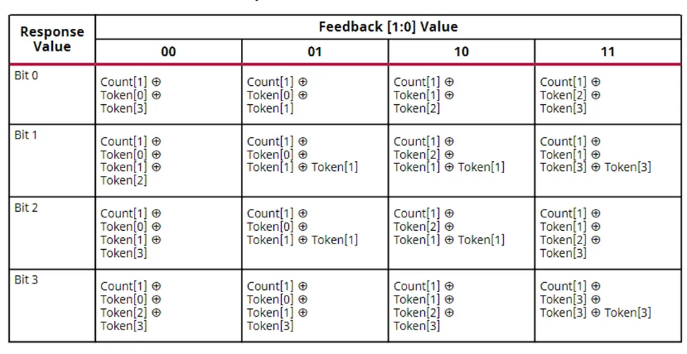
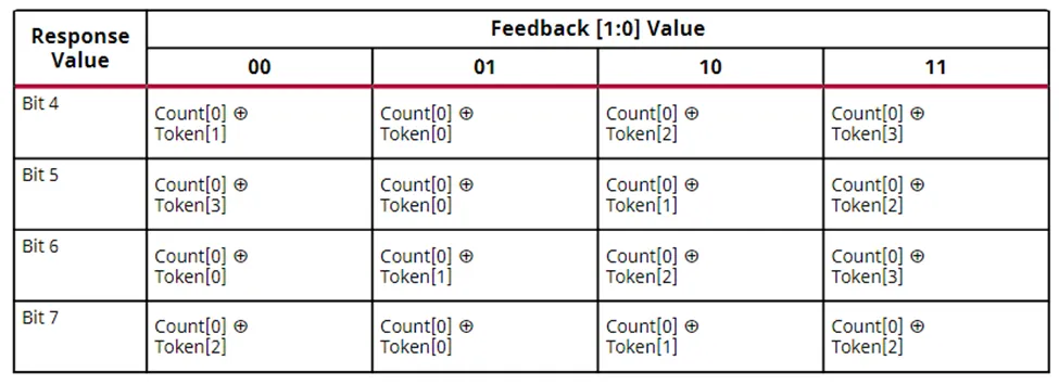
For example, if the feedback value is 3, the computation of each response bit follows the last column labeled "11" in the table. Bit 0 of the response is computed by XORing ACNT bit 1 with seed bit 2 and seed bit 3. After computing all eight response bits, writing them into the Token_Resp register completes one Q&A cycle.
After configuring watchdog settings, window times, and Q&A seed and feedback values, the watchdog only starts timing after the first response has been executed. Within the first window the user must complete the second and third responses, with their intervals controlled by the user. Once those two responses are completed, the sequence immediately moves to the second window even if the first window has not yet expired. The user must complete the fourth response within the second window. If the fourth response is completed during the second window, the sequence immediately returns to the first window even if the second window has not expired. If the fourth response is not completed during the second window, the sequence still returns to the first window and subsequent responses must continue following the fourth-response requirement.
A limited number of response failures is allowed. The failure count is stored in the Fail count bits of the Enable_and_Status register. Each failure increments the failure count by 1; each successful response decrements it by 1. When the failure count reaches 7, any further failure generates an error event and sends a system error to PSM and PMC.
4. Summary
The watchdog module in Versal devices provides a rich set of features, progressing from simple application use to advanced safety mechanisms, allowing users to protect their systems according to different application scenarios.


