 ALLPCB


Introduction
Surface mount device (SMD) microcontrollers have become essential for modern electronic projects, especially among hobbyists building compact prototypes and custom boards. These components feature tiny pitches, often as small as 0.4mm or 0.5mm, making soldering challenging without proper techniques. Mastering SMD microcontroller soldering techniques allows hobbyists to achieve reliable connections on dense PCBs, avoiding common pitfalls like shorts or weak joints. This guide provides a practical, step-by-step approach tailored for home setups, covering everything from preparation to rework. Whether using a reflow oven or hand tools, you will learn methods that ensure functionality in your projects. By following these steps, hobbyists can confidently assemble professional-grade boards.
Why Surface Mount Microcontroller Soldering Matters for Hobbyists
SMD microcontrollers, such as those in QFN or BGA packages, enable smaller footprints and higher performance compared to through-hole alternatives. Soldering small pitch microcontrollers demands precision to align pads perfectly and prevent defects that could render a board useless. For electronic hobbyists, this skill opens doors to advanced projects like wearables, IoT devices, and robotics, where space is at a premium. Poor soldering leads to issues like tombstoning or insufficient solder volume, wasting time and components. Adhering to established practices ensures boards pass basic functionality tests right away. Ultimately, reliable SMD soldering builds confidence and efficiency in prototyping workflows.
Understanding the Technical Principles of SMD Soldering
SMD soldering relies on the physics of solder melting and wetting, where flux in the solder paste cleans surfaces for strong metallurgical bonds. Microcontrollers with fine-pitch leads require controlled heat to avoid damaging sensitive silicon dies or warping thin PCBs. Solder paste, a mix of alloy particles, flux, and activators, is key for uniform deposition in reflow processes. Hand soldering introduces variables like tip temperature and dwell time, which must stay within safe limits to prevent overheating. Thermal profiles mimic industrial ovens but scale down for hobby tools. These principles form the foundation for all SMD microcontroller soldering techniques.
Standards like IPC J-STD-001 define requirements for soldered joints, including fillet formation and void limits, ensuring mechanical and electrical integrity. Heat transfer during soldering affects intermetallic compound growth, which strengthens bonds but can become brittle if excessive.
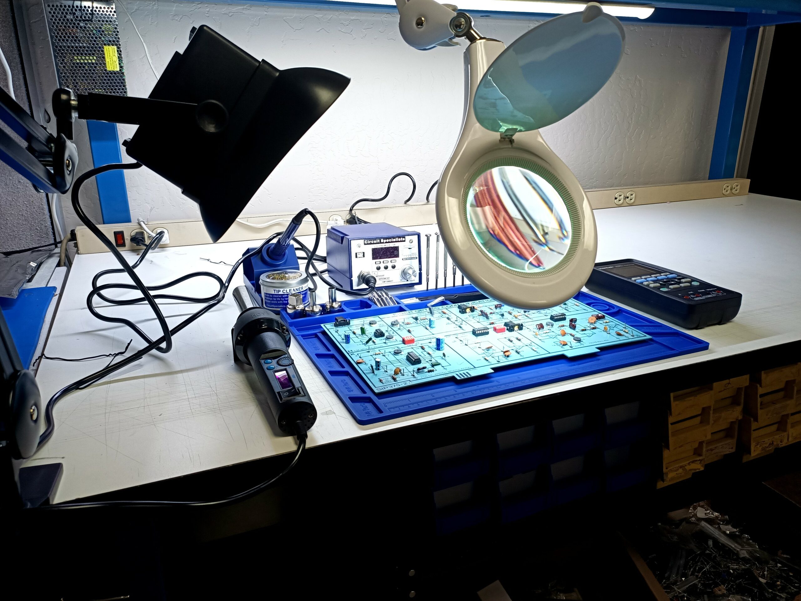
Preparing Your Workspace and Materials
Start by organizing a clean, static-free workstation with good lighting and ventilation to handle fumes from flux. Gather essentials: fine-pitch soldering iron with temperature control (ideally 300-350°C), flux, solder wire or paste, tweezers, isopropyl alcohol for cleaning, and a hot air station for rework. For solder paste microcontroller PCB assembly, a stencil matching your PCB design is invaluable, though hobbyists can improvise with syringes for small jobs. Inspect the PCB for cleanliness and flatness, as contaminants cause poor wetting. Pre-bake components if needed to remove moisture, following manufacturer guidelines. Proper preparation minimizes defects from the outset.
Verify pad sizes align with the microcontroller datasheet; oversized pads risk bridging on small pitches.
Step 1: Applying Solder Paste
Solder paste application sets the stage for successful reflow soldering microcontroller processes. Use a metal stencil or hypodermic needle to deposit paste precisely on pads, aiming for 100% coverage without excess. For soldering small pitch microcontroller leads, align the stencil perfectly using fiducials on the PCB. Scrape paste evenly with a squeegee at 45 degrees, then lift the stencil slowly to avoid smearing. Clean the stencil between prints with alcohol. Inspect under magnification for uniform bricks of paste, adjusting viscosity if it spreads too much.
Too little paste leads to open joints, while blobs invite bridges during reflow.
Step 2: Component Placement
Precise placement is critical for SMD microcontroller soldering techniques. Use tweezers or a vacuum pickup tool to position the component, ensuring all leads align with pads. For fine-pitch parts, a magnifying glass or USB microscope helps verify alignment before committing. Apply minimal downward pressure to seat it, then tack one corner with hot air or iron to hold position. Double-check orientation via pin 1 marker. Misalignment by even 0.1mm can cause reflow failures.

Step 3: Reflow Soldering Process
Reflow soldering microcontroller assemblies involves a controlled thermal profile: preheat to 150°C for 60-90 seconds, soak at 180°C, ramp to peak 220-245°C for 30-60 seconds, then cool gradually. Hobbyists use toaster ovens or hot plates with thermocouples for monitoring. Place the PCB on a heat-resistant surface, applying low airflow to prevent movement. Watch for solder melting and joints forming shiny fillets. Overheating risks delamination, so profile your setup first with thermocouples. This method excels for multi-lead devices.
IPC-A-610 outlines acceptability criteria, such as smooth solder surfaces and no cracks.
Step 4: Hand Soldering for Precision Work
Hand soldering SMD microcontroller suits low-volume hobby work or touch-ups. Tin the iron tip with 0.3-0.5mm wire, apply flux to pads and leads, then drag solder along pins quickly. Maintain 320°C tip temperature, dwelling 1-2 seconds per pin to avoid heat buildup. Use a drag soldering technique for rows of pins, letting excess wick away. Clean flux residue promptly to prevent corrosion. Practice on scrap boards builds speed and consistency.
For ultra-fine pitches, pre-tin pads lightly before placing the chip.
Inspection and Testing
Post-soldering, inspect joints visually and with a multimeter for continuity. Look for cold joints (dull, concave), bridges (shiny links between pads), or voids under X-ray if available. Electrical tests confirm no shorts; power up gradually to check for heat or smoke. Mechanical stress tests, like finger pressure, verify bond strength. Rework any issues immediately. Thorough inspection catches 90% of problems early.
Reworking SMD Microcontrollers
Rework SMD microcontroller becomes necessary for fixes or prototypes. Use hot air at 350°C with low flow to heat all leads evenly, lifting with tweezers once reflowed. Clean pads with solder wick and flux, then reapply paste or wire for reinstallation. Avoid excessive heat cycles, limited to 3-5 per component. For BGA types, reflow tools with bottom preheat prevent warpage. Document changes for repeatability.
J-STD-020 provides guidelines on reflow sensitivity to prevent popcorning during rework.
Common Troubleshooting Tips
Bridges often stem from excess paste; use less volume or no-clean flux for easier cleanup. Tombstoning happens from uneven heating, fixable by preheating the board underside. Weak joints indicate poor flux activation, so refresh paste if delayed. Overheated chips show discoloration; reduce peak temps next time. For hand soldering small pitch microcontroller leads, curved tips improve access. Systematic troubleshooting saves components.
Conclusion
Mastering surface mount microcontroller soldering empowers hobbyists to tackle compact, high-density designs with confidence. From solder paste application to reflow and rework, each step builds on precise preparation and controlled heat. Key SMD microcontroller soldering techniques like stencil printing and thermal profiling ensure reliable results. Hand methods offer flexibility for quick fixes. Regular practice and inspection refine skills over time. Apply these steps to elevate your projects from prototypes to polished builds.
FAQs
Q1: What are the best SMD microcontroller soldering techniques for beginners?
A1: Start with solder paste and a reflow oven for even heating on small pitch parts. Practice hand soldering SMD microcontroller on larger QFP packages first to build dexterity. Use flux liberally and inspect joints under 10x magnification. Avoid high heat to prevent damage. This approach minimizes bridges and ensures strong bonds for hobby projects.
Q2: How do I apply solder paste for microcontroller PCB assembly?
A2: Print paste through a stencil aligned to fiducials for uniform coverage on pads. Scrape at 45 degrees, lift slowly, and verify bricks visually. For manual work, use a syringe for precision on soldering small pitch microcontroller leads. Clean up smudges with a brush before placement. Proper application prevents voids in reflow soldering microcontroller processes.
Q3: When should I use rework for SMD microcontrollers?
A3: Opt for rework SMD microcontroller when joints fail inspection or the board malfunctions. Hot air removes the part evenly, followed by pad cleaning. Reinstall with fresh paste, limiting cycles to avoid degradation. Test thoroughly post-rework. This saves prototypes without scrapping the entire PCB.
Q4: Can hobbyists do reflow soldering microcontroller at home safely?
A4: Yes, with a controlled oven or hot plate and thermocouple monitoring. Follow a profile peaking at 240°C, ensuring ventilation for fumes. Preheat to activate flux evenly. This matches professional reflow soldering microcontroller outcomes for hand soldering SMD microcontroller alternatives.


