 ALLPCB


The past decade has seen rapid advances in smartphones, wearable devices, and digital health. Breakthroughs in electronics and technologies such as cloud computing, artificial intelligence (AI), the Internet of Things (IoT), and 5G have accelerated the adoption of digital health. Some vital signs monitoring (VSM) functions are already integrated into phones, watches, and other wearable devices, bringing these capabilities to a wider population.
Market drivers and design challenges
Growing health awareness has increased demand for compact, high-precision devices capable of measuring multiple vital signs and health metrics, such as temperature, heart rate, respiration rate, blood oxygen saturation (SpO2), blood pressure, and body composition. The COVID-19 pandemic further increased demand for multi-parameter vital signs monitors used in hospitals and home settings. Integrating multiple sensing functions into small devices poses challenges including reduced form factor, lower power consumption, and improved multi-parameter performance. A single analog front end (AFE) solution can address these challenges by serving as a centralized multi-parameter VSM hub that supports synchronous measurements while offering low noise, high signal-to-noise ratio (SNR), small footprint, and low power consumption. The following sections describe a representative single AFE architecture and its key features.
AFE overview
The ADPD4100/ADPD4101 is a multi-mode sensor AFE with eight analog inputs and support for up to 12 programmable time slots per sampling cycle, enabling 12 independent measurements within one sampling period. The eight analog inputs can be multiplexed into a single channel or configured as two independent channels, sampled either single-ended or differential to support two sensors simultaneously. Eight LED drivers can drive up to four LEDs concurrently. These LED drivers are current sinks and are independent of LED supply voltage and LED type. The device includes two pulsed voltage sources for voltage excitation. The analog signal path comprises a transimpedance amplifier (TIA), band-pass filter (BPF), integrator (INT), and analog-to-digital converter (ADC) stages. The digital module provides multiple operating modes, programmable timing, general-purpose I/O (GPIO) control, module averaging, and optional cascaded comb filters (CIC) of second to fourth order. Data can be read directly from data registers or via FIFO.
Two interface variants exist: one with an I2C interface and one with an SPI port. The ADPD4100/ADPD4101 includes features for optical measurements such as automatic ambient light suppression enabled by a synchronous modulation scheme with pulses as short as 1 μs, removing the need for external control loops, DC current subtraction, or digital postprocessing. Higher decimation factors can be used to increase output SNR. A sub-sampling feature allows selected time slots to run at a lower sampling rate than the programmed rate to save power (power scales with sampling rate). A TIA upper-limit detection feature uses a voltage comparator on the TIA output pin to set an interrupt bit when the TIA input exceeds typical operating limits.
These AFEs can act as a hub for electrical and optical sensors in wearable health and fitness devices, suitable for heart rate and heart rate variability (HRV) monitoring, blood pressure estimation, stress and sleep tracking, and SpO2 measurement. Multiple operating modes accommodate different sensor measurements in medical and consumer health applications, including but not limited to photoplethysmography (PPG), electrocardiography (ECG), electrodermal activity (EDA), body composition, respiration, temperature, and ambient light sensing.
PPG measurement
Photoplethysmography detects blood-volume changes in the microvascular bed of tissue associated with each cardiac cycle. Total light absorption correlates with blood-volume changes caused by systolic and diastolic events, producing the PPG signal. PPG is performed by pulsing LEDs into tissue and collecting reflected or transmitted light with a photodiode that converts light to photocurrent. The ADPD4100/ADPD4101 processes and measures the photocurrent and outputs digital PPG signals. The AFE can be flexibly configured, without hardware changes, into four operating modes for different PPG measurement scenarios: continuous connection mode, multiple-integration mode, floating mode, and digital-integration mode.
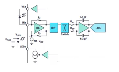
Figure 1. Typical PPG circuit
Continuous connection mode
Continuous connection mode is the typical PPG measurement mode. It provides the best ambient light suppression and high SNR. It operates well at charge transfer ratios (CTR, photocurrent to LED current ratio) from about 5 nA/mA down to 10 nA/mA and delivers 95 dB to 100 dB DC SNR, which can be increased by raising the decimation factor. This mode uses the complete analog signal path: TIA + BPF + INT + ADC. Incoming charge is integrated once per ADC conversion. During a single excitation event, the integrator uses much of its dynamic range while integrating charge from the sensor response. After a preconditioning period, the TIA remains continuously connected to the input, so the input signal is not modulated. To reduce noise, the photodiode anode is preconditioned to the TIA reference voltage (TIA_VREF). TIA_VREF is often set to 1.27 V to maximize TIA dynamic range. The photodiode cathode is connected to a cathode voltage source (VCx); commonly this supplies TIA_VREF + 215 mV to the photodiode cathode to create a 215 mV reverse bias. This reduces signal-path noise and photodiode capacitance. Typical LED pulse width in this mode is 2 μs; short LED pulses provide optimal ambient light suppression. Doubling the number of LED pulses increases SNR by 3 dB. Enabling integrator chopping removes low-frequency noise from the integrator and typically yields the highest SNR. Higher TIA gain reduces equivalent input-referred noise but reduces TIA dynamic range. TIA dynamic range is calculated as: dynamic range = TIA_VREF / TIA_gain. To raise ADC saturation level, reduce TIA gain or increase integrator resistor. A higher integrator resistor lowers noise but a lower integrator resistor increases ambient-light margin.
Multiple integration mode
Multiple integration mode is similar to continuous connection mode but integrates incoming charge multiple times per ADC conversion. This mode yields higher SNR under low light because each excitation event uses only a fraction (sometimes under 50%) of the integrator dynamic range. By integrating multiple times before ADC conversion, the mode leverages a larger integrator dynamic range. Doubling the number of integrations per ADC conversion raises SNR by 3 dB, equivalent to doubling pulses. This mode is typically used with small inputs and the highest TIA gain. It is suitable for CTR below 5 nA/mA where good ambient light suppression is required.
Floating mode
Floating mode also targets low-light situations and enables noiseless charge accumulation on the photodiode. The photodiode is disconnected from the AFE (hence "floating") to accumulate photogenerated charge without added noise. The AFE is then reconnected, and the accumulated charge is transferred to the AFE for integration in a way that allows maximum charge processing per pulse with minimal added signal-path noise. Because modulation pulses are short, charge transfer occurs quickly and results in a small noise increase from the signal path. Floating time can be increased to raise signal level, but the photodiode capacitance limits the total storable charge. In this mode, the band-pass filter is bypassed because the waveform shape produced when transferring photodiode charge may vary with device and conditions; bypassing the BPF ensures reliable alignment between the signal and the integration sequence. Floating mode does not provide strong ambient light suppression and is limited by photodiode capacitance, but it delivers efficient, low-noise measurements in extremely low-light conditions.
Mode selection under low-light conditions
For CTR < 5 nA/mA in low light, floating mode is typically preferred since it has lower noise than multiple integration mode, which requires more integration cycles and thus increases TIA and integrator noise contributions. With the BPF off and shorter measurement times, floating mode also offers higher power efficiency than multiple integration mode, yielding better SNR per watt.
If the photodiode has leakage or if ambient light is significant, multiple integration mode is preferred. A leaky photodiode cannot be used in floating mode because charge leaks away before the quick charge transfer occurs. Strong ambient light also makes floating mode unsuitable because ambient illumination dominates the charge the photodiode can store. Multiple integration mode inherently provides excellent ambient-light suppression due to use of the BPF and short LED pulses.
Digital integration mode
All modes above use the integrator to integrate incoming charge. In digital integration mode, ADC samples are digitally integrated instead: the integrator is configured as a buffer. This mode operates across two periods: a light period where the LED is on and a dark period where the LED is off. ADC samples are collected at 1 μs intervals in both periods and digitally summed. The signal is computed by subtracting the integrated dark samples from integrated light samples. Digital integration supports longer LED pulses and is suited to slow photodiode responses that require longer pulses. The BPF is bypassed and disabled. Digital integration delivers optimal power efficiency and can achieve the highest SNR levels. However, because it uses longer LED pulses and bypasses the BPF, ambient light suppression is inferior to continuous connection mode. Digital integration does not support simultaneous sampling of two channels in the same time slot. This mode can support 100+ dB DC SNR.
Digital integration trade-offs
Continuous connection mode is typically preferred for PPG because it provides high SNR and excellent ambient light suppression when CTR > 5 nA/mA. However, digital integration can achieve the highest SNR and best SNR-per-watt efficiency. If ambient light is not a concern and the target DC SNR exceeds 85 dB, digital integration may be chosen to efficiently reach high SNR. For target DC SNR below 85 dB, power savings with digital integration are not significant compared with continuous connection mode.
In summary, digital integration is suitable when the photodiode requires long pulses due to slow response, or when simultaneous two-channel sampling within a single time slot is not required. It is also a power-efficient choice when ambient light is not an issue and target DC SNR is above 85 dB.
PPG applications
PPG has become more important for vital signs monitoring and health diagnostics during the COVID-19 pandemic. Multi-metric monitoring is critical for detection and assessment. Important measurements include heart rate monitoring (HRM), heart rate variability (HRV), and blood oxygen saturation (SpO2), which can be acquired with pulse oximetry and related techniques.
Optical, noninvasive SpO2 monitoring (pulse oximetry) has become valuable for detecting hypoxia in COVID-19 patients. Hypoxia indicates insufficient oxygen supply to tissues, a key symptom of COVID-19, and can cause tachycardia. Therefore, optical, noninvasive heart-rate monitoring is also critical for detection.
For future wearable devices, integrating multiple measurement functions is advantageous. The ADPD4100/ADPD4101 supports various sensor inputs including temperature, ECG, and respiration measurements, enabling a complete multi-parameter VSM platform with a single sensor AFE.
Pulse oximetry — SpO2 measurement
Pulse oximetry uses red light (commonly 660 nm) and infrared (IR) light (commonly 940 nm). Deoxygenated hemoglobin absorbs primarily at 660 nm while oxygenated hemoglobin absorbs primarily at 940 nm. The photodiode senses unabsorbed light and the signal is separated into DC and AC components. The DC component represents absorption from tissue, venous blood, and non-pulsatile arterial blood; the AC component represents pulsatile arterial blood. SpO2 percentage is calculated from the ratio of ratios derived from these components.
The ADPD4100/ADPD4101 can be configured to measure red and IR responses using any two time slots, enabling SpO2 measurement. Remaining time slots can measure other LED wavelengths and support ECG, lead-off detection, respiration, and other sensor measurements.
Heart rate monitoring
Heart-rate monitoring is also important in COVID-19 detection because hypoxia can prompt the heart to beat faster to supply oxygen to tissues. Heart-rate monitoring is also useful for detecting cardiac issues and tracking fitness activity.
Green LEDs at approximately 540 nm are generally preferred for heart-rate monitoring due to a higher modulation index compared with red or IR LEDs, producing stronger PPG signals. Green also provides adequate CTR, keeping power consumption reasonable.
AC SNR relates to signal quality and can be calculated as DC SNR multiplied by the modulation index. For example, with a modulation index of 1% and 95 dB DC SNR, the AC SNR corresponds to about 55 dB.
ECG measurement
ECG measurement is incorporated into wearables such as spot-check watches and continuous-monitoring chest patches. These devices typically use dry electrodes made of metal or other conductive materials. The challenge with dry electrodes is high electrode-skin contact impedance and relatively high overpotentials.
Conventional instrument-amplifier-based ECG solutions use buffers to mitigate the effects of signal attenuation from high electrode-skin impedance. Right-leg drive (RLD) techniques use a third electrode to drive a reference voltage back into the body to suppress common-mode voltages from the body, electrodes, and cables.
For ECG, the ADPD4100/ADPD4101 implements a different approach that uses a passive RC sampling circuit to track differential voltage across a pair of electrodes. The passive RC circuit can be implemented with just three external components: two resistors (RS) and one capacitor (CS). Each ECG data sample is acquired in two steps.
In the charge phase, the input pins (IN7 and IN8) float. If the charge time exceeds 3τ, the charge on CS is proportional to the differential voltage across the electrodes, where τ is the time constant defined by RS and CS, τ = 2RSCS. In the charge-transfer phase, the capacitor is connected to the TIA and the charge is transferred to the AFE for measurement. This charge-measurement-based ECG approach has advantages including no buffer and no third electrode for RLD, reduced system size due to fewer external components, and power savings.
Using the AFE's design flexibility, lead-off detection can be added to this ECG solution via a bioimpedance method. The lead-off detection circuit injects pulses into one electrode and receives current on the other. If one or both electrodes detach from skin, the current path is broken and no current is received. ECG traces and the received lead-off detection current can be measured in separate time slots: ECG in time slot A and lead-off detection in time slot B.
Traditional lead-off detection in ECG solutions uses pull-up resistor circuits that affect ECG input impedance. In contrast, bioimpedance-based lead-off detection performed in separate time slots does not affect ECG measurements. Using this DC-coupled circuit, ECG signals are restored immediately once electrode contact is re-established.
Impedance-based respiration measurement
Respiration measurement with the ADPD4100/ADPD4101 detects changes in lung bioimpedance during inhalation and exhalation. Monitoring respiration is useful in intensive care units and during sleep to support patient management and provide timely alerts. This is important for patients with respiratory diseases and sleep apnea, a major public health concern.
As the patient breathes, lung volume expands and contracts, changing chest impedance. By injecting current into the thoracic path and measuring the resulting voltage drop, impedance changes can be tracked. A reference design using two electrodes supports both ECG and respiration monitoring. Synchronized ECG, respiration-related impedance waveforms, and PPG can be recorded with ECG and respiration measured via stainless-steel dry electrodes on the wrists and PPG measured with a green LED.
Figure 5. ECG and respiration measurement. (a) External circuit using Kelvin detection for sleep floating ECG and respiration measurement. (b) Example of synchronized ECG, respiration, and PPG measurements.
Summary
Vital signs monitoring has expanded into the consumer space via smart wearables. Data from wearable devices can play a significant role in health and disease management. To meet market needs and broaden device adoption, designers must balance cost, size, and power. A single AFE such as the ADPD4100/ADPD4101 can reduce the number of ICs required in a multi-parameter VSM system, lowering cost and footprint. Systems designed around a single AFE can also generate synchronous data, removing synchronization burdens between separate sensor ICs.
References
1. "Sleep apnea surge threatens public health." American Academy of Sleep Medicine (AASM). September 2014.


