ALLPCB


Overview
This article continues the discussion of the Additional spectrum emission mask (A-SEM). "Additional" refers to extra requirements a network may impose on a UE. The concept was introduced in the 5G UE RF test standard (A-MPR-1) as Additional Maximum Power Reduction (A-MPR). A-SEM is the additional spectrum emission mask associated with those network instructions.
Modern smartphones must satisfy many standard and additional test requirements across multiple bands and deployment scenarios. A-SEM defines extra spectrum emission limits that apply in specific cases, such as certain bands or handover/broadcast scenarios.
01 Understand NS
To understand what A-SEM measures, review the concept of NS:
NS: network signalling
Additional spectrum emission requirements are signalled by the network to indicate that the UE shall meet an additional requirement for a specific deployment scenario as part of the cell handover or broadcast message.
NS is a specific network signalling value. Different NS values represent different network requirements. In effect the network can instruct the UE to meet additional emission limits. Each additional emission requirement is associated with a unique AdditionalSpectrumEmission value in RRC signaling. These requirements are typically applied in specific deployment scenarios or frequency ranges and are broadcast as part of cell information or handover procedures.
The following table (from section 6.2) lists NS values by band:
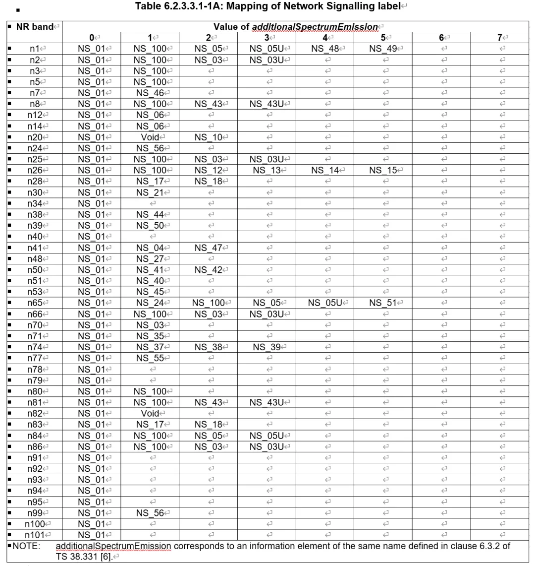
These NS entries correspond to three main categories: one is the A-SEM requirements described in section 6.5.2.3 (applicable to NR power class 2 and 3 not supporting Tx diversity for R15 and later, and NR power class 1 for R15 and later). For example:
NS_35;NS_04:n41 SEM;NS_03;NS_03U;NS_06;NS_07;notcomplete;NS_27;NS_21: applicable to Release 17 and later modified MPR-Behavior;
The additional requirements listed in the NS table are implemented using A-MPR. Other NS entries address additional ACLR requirements (section 6.5.2.4.2) and additional spurious emission requirements (section 6.5.3), which will be covered when ACLR and spurious emissions are discussed.
Because these values are delivered in RRC signaling, the corresponding information element is defined in 38.331 as follows:
AdditionalSpectrumEmission ::= INTEGER (0..7)
Other information elements reference AdditionalSpectrumEmission, for example FrequencyInfoUL and NR-NS-PmaxList:
FrequencyInfoUL ::= SEQUENCE { frequencyBandList MultiFrequencyBandListNR OPTIONAL, -- Cond FDD-OrSUL absoluteFrequencyPointA ARFCN-ValueNR OPTIONAL, -- Cond FDD-OrSUL scs-SpecificCarrierList SEQUENCE (SIZE (1..maxSCSs)) OF SCS-SpecificCarrier, additionalSpectrumEmission AdditionalSpectrumEmission OPTIONAL, -- Need S p-Max P-Max OPTIONAL, -- Need S frequencyShift7p5khz ENUMERATED { true } OPTIONAL, -- Cond FDD-TDD-OrSUL-Optional ... }
NR-NS-PmaxList ::= SEQUENCE (SIZE (1..maxNR-NS-Pmax)) OF NR-NS-PmaxValue NR-NS-PmaxValue ::= SEQUENCE { additionalPmax P-Max OPTIONAL, -- Need N additionalSpectrumEmission AdditionalSpectrumEmission }
02 A-SEM Test Requirements
Several NS values apply to A-SEM, including: NS_35, NS_04, NS_03, NS_03U, NS_06, NS_07, NS_27, NS_21. For brevity this section uses NS_04 as an example to illustrate A-SEM test requirements.
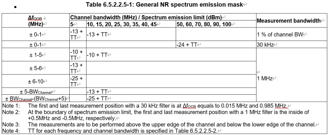
For comparison, the general SEM requirements previously discussed are listed first. This illustrates how the additional requirements differ from the general case.
General SEM test requirements:
A-SEM test requirements for NS_04:
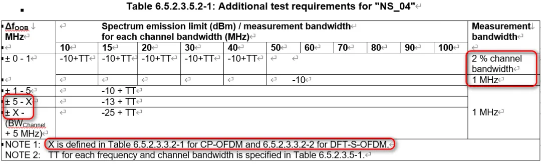
Test time-to-transmit (TT) values are the same; the main differences are highlighted in the annotated table areas.
Measurement bandwidth changes are significant. Limits are specified as integrated power within a measurement bandwidth, so direct comparison across different bandwidths requires conversion to a common measurement bandwidth. For example, consider SEM within Delta f OOB = ±(0–1) MHz using a 100 MHz channel bandwidth. The general SEM limit is -24 dBm/30 kHz, while NS_04 specifies -10 dBm/MHz. To compare, convert -10 dBm/MHz to a 30 kHz measurement bandwidth:
-10 dBm/MHz = -10 dBm - 10*log10(1000/30) dB = -10 dBm - 15.23 dB = -25.23 dBm/30 kHz
Thus, NS_04 is more stringent than the general SEM limit by 1.23 dB at 100 MHz channel bandwidth within the ±(0–1) MHz range.
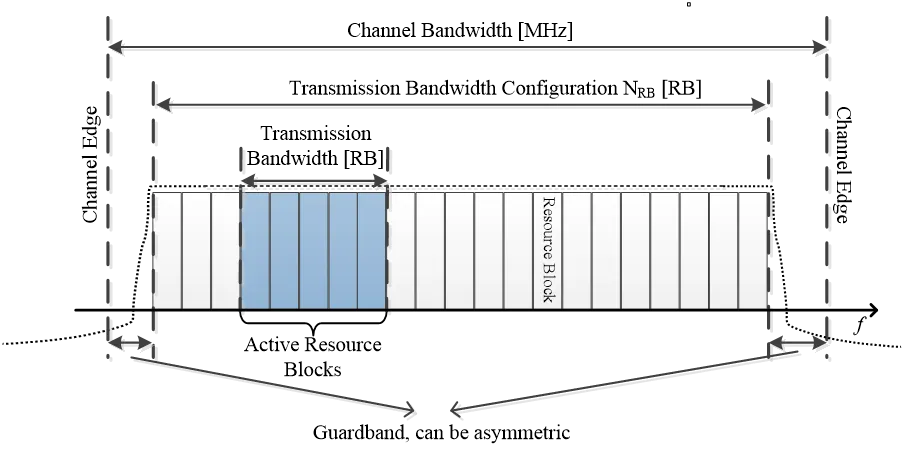
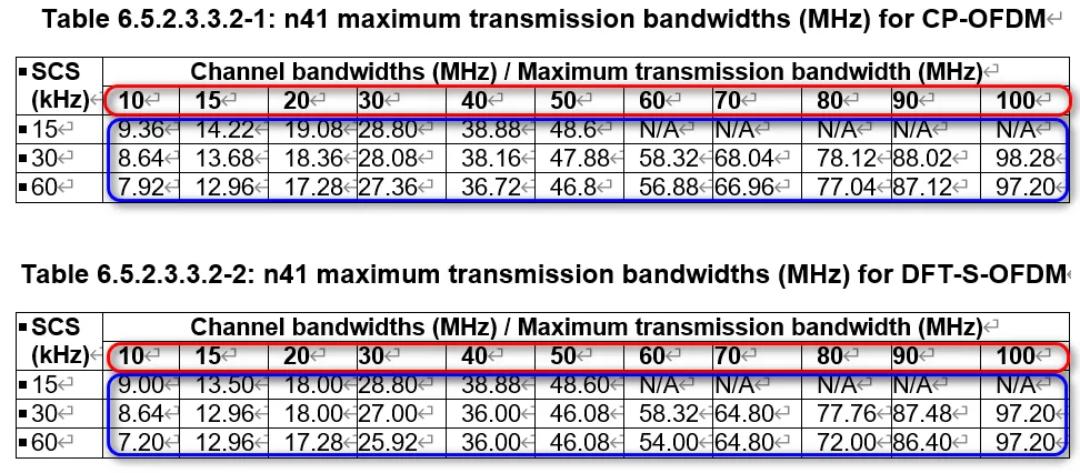
In the general SEM table, the term "BWchannel" refers to the channel bandwidth allocation (for example 10 MHz, 20 MHz, ..., 100 MHz). In the NS_04 table the term X denotes the Maximum transmission bandwidth (NRB * SCS * 12 / 1000). For CP-OFDM and DFT-S-OFDM the definition of X varies by numerology (SCS). The channel bandwidth values and the corresponding maximum transmission bandwidths are shown in the tables below; X is generally smaller than BWchannel. For example, the general SEM limit from 5 MHz to 100 MHz is -13 dBm/MHz, while NS_04 has -13 dBm/MHz only up to a narrower band (for example up to 97.2 MHz at 30 kHz SCS in the 100 MHz allocation). Even when the numeric limits match, the applicable bandwidth ranges can be narrower under NS_04, making the overall requirement more restrictive.
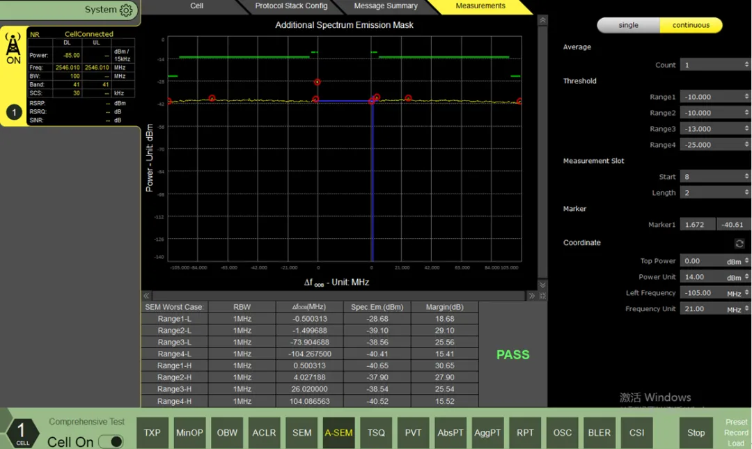
Below is an example test measurement for band n41 using the NS_04 additional spectrum template. Compare the measurement results to the NS_04 limit table to determine compliance.