 ALLPCB


Introduction
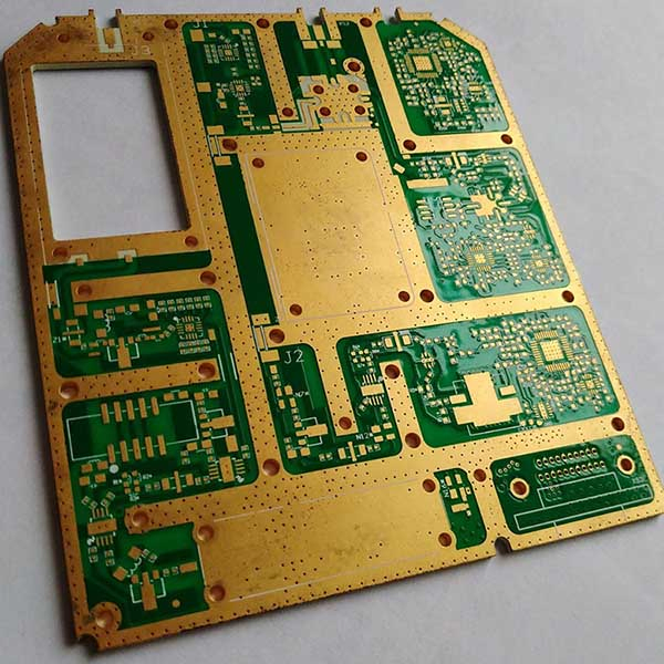
Rogers PCBs play a vital role in high-frequency applications such as radar systems, 5G infrastructure, and microwave circuits, where low signal loss and dimensional stability are essential. These materials, often ceramic-filled composites, demand precision during fabrication to maintain electrical performance and mechanical integrity. The Rogers PCB manufacturing process introduces unique hurdles compared to standard FR4 boards, including drill wear, resin smear, and bonding inconsistencies. Engineers must address these to achieve reliable yields and meet stringent performance specs. This article explores key challenges in drilling, lamination, etching, and surface finishing, offering factory-driven solutions aligned with industry practices.
Why Rogers PCBs Demand Specialized Manufacturing
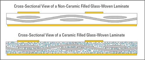
Rogers laminates excel in high-frequency environments due to their stable dielectric properties and low moisture absorption, making them ideal for demanding RF designs. However, their reinforced structure leads to fabrication difficulties that can compromise hole quality, layer alignment, and trace integrity. For instance, ceramic fillers accelerate tool wear and create rough hole walls, while the resin systems require careful thermal management to prevent voids or delamination. These issues directly impact signal integrity and assembly yields in electrical engineering projects. Understanding the Rogers PCB manufacturing process ensures designs translate effectively from simulation to production. Factory experience shows that proactive process controls minimize defects and optimize costs.
Challenges in Rogers PCB Drilling Techniques
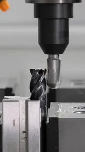
Drilling Rogers materials presents significant hurdles due to the abrasive ceramic content, which causes rapid drill bit wear and resin smear on hole walls. Smear, a common defect, coats copper lands and hinders plating adhesion, often traced to excessive heat from high speeds or inadequate chip evacuation. Rough hole walls result from filler particles, affecting aspect ratios in multilayer stacks. Per IPC-9121A guidelines for fabrication troubleshooting, drill smear stems from undercured resin or improper parameters, demanding verification through plated-through hole inspections. Factory operators mitigate this by using peck drilling cycles with controlled retract rates to clear debris effectively. Standard entry and exit materials, like pressed phenolics, provide support without contaminating the stack.
Rogers PCB drilling techniques also benefit from plasma or chemical desmear post-drilling, especially in multilayer boards where L2 features require clean surfaces. Mechanical deburring risks damaging delicate walls, so light chemical methods or CF4/O2 plasma etching preserve integrity. Laser drilling with UV or CO2 lasers offers alternatives for microvias, reducing smear in high-density designs. Inspecting hit counts via PTH quality, rather than tool visuals, ensures consistent performance across production runs. These steps align with standard practices to achieve acceptable hole registration and plating uniformity.
Optimizing Lamination Rogers Processes
Lamination in Rogers PCB fabrication requires precise control to avoid voids, resin starvation, or bow and twist, particularly with low glass content materials prone to warpage under unbalanced copper. Thermoset hydrocarbon resins demand compatible prepregs or bondplies, with oxide treatments on cores enhancing adhesion. Factory cycles follow adhesive-specific parameters to ensure full flow without excessive squeeze-out. IPC-6012E qualification specs emphasize uniform bonding for rigid boards, verifying no delamination under thermal stress. Multi-layer hybrids with FR4 often use Rogers as cores or caps, necessitating matched CTE to prevent cracks during press cycles.
Pre-baking removes moisture, critical for low-absorption Rogers laminates, while vacuum-assisted pressing expels volatiles. Unbalanced constructions exacerbate twist, so symmetric stack-ups and pinned tooling maintain registration. Post-lamination, cross-section analysis confirms void-free interfaces. These factory-driven insights ensure lamination Rogers processes yield stable panels ready for imaging. Engineers benefit from first-article validation to scale production confidently.
Precision in Etching Rogers PCB
Etching Rogers PCB demands compensation for differential etch rates between copper and resin, risking underetch or overetch that widens traces or creates shorts. Post-drill desmear leaves residues that, if not managed, lead to plating skips or weak barrels. Aggressive etchback loosens fillers and attacks resin near copper, compromising multilayer integrity. Factories preserve the post-etch surface, which bonds excellently to solder masks without additional treatment. Standard strip-etch-strip sequences work well, but spray etching ensures uniform attack in high-aspect features.
Per IPC-A-600K acceptability criteria, etched traces must show clean edges without ragged sidewalls or unetched islands. Artwork scaling accounts for isotropic undercuts, verified via pilot lines. Chemical preparation before imaging, like microetch, boosts resolution on reverse-treated foils. These techniques in etching Rogers PCB maintain impedance control essential for RF performance. Avoiding mechanical scrubs post-etch prevents filler dislodgement.
Surface Finish Rogers: Key Considerations
Surface finish Rogers applications prioritize adhesion and solderability while preserving low-loss properties. Common defects include poor wetting from oxidation or inadequate cleaning, especially on LoPro copper foils. Organic cleaners followed by microetch prepare surfaces for plating without damaging the laminate. High Tg minimizes smear during double-sided processing, but multilayers may need desmear. Compatibility spans OSP, immersion finishes, and electrolytic platings, with copper flash aiding high-aspect holes.
Factories select finishes based on assembly needs, ensuring IPC standards for thickness and appearance. Post-etch preservation enhances direct solder mask bonding. Baking after sodium treatments stabilizes for metallization. Surface finish Rogers thus supports reliable HASL or ENIG without special processes. Verification via thermal cycling confirms long-term reliability.
Best Practices for Rogers PCB Manufacturing Process
Implement FIFO inventory and lot tracing to maintain material consistency, as Rogers laminates are sensitive to storage conditions. Conduct incoming inspections for oxidation or dimensional stability before processing. Pilot runs establish scaling factors for etching and drilling, reducing scrap in volume production. Hybrid stacks require CTE-matched layers to avoid warpage per IPC-9121A troubleshooting for bow/twist. Plasma desmear suits CAF-sensitive designs, while chemical options scale for throughput.
Tooling with sharp carbide bits and controlled feeds extends life in drilling. Symmetric layups and vacuum lamination prevent voids. Post-process bakes stabilize panels before routing. These factory best practices streamline the Rogers PCB manufacturing process. Electrical engineers can specify tolerances informed by these insights for optimal yields.
Troubleshooting Common Fabrication Issues
Drill smear often signals excessive heat; reduce feeds and inspect stacks for cooling. Delamination traces to moisture; enforce pre-bake protocols. Underetch in etching points to weak chemistry; monitor conveyor speeds. Warpage post-lamination? Balance copper and use fixtures. IPC-9121A provides root-cause trees for these, guiding corrective actions like parameter tweaks or supplier audits. Cross-sections reveal hidden defects early.
Conclusion
Overcoming challenges in Rogers PCB fabrication hinges on tailored drilling techniques, controlled lamination, precise etching, and robust surface finishes. Factory alignment with standards like IPC-6012E and IPC-A-600K ensures qualification and acceptability. These processes preserve the material's high-frequency advantages, delivering reliable boards for critical applications. Engineers gain from proactive pilots and inspections to bridge design and production. Precision manufacturing elevates Rogers PCBs from challenging to competitive.
FAQs
Q1: What are the main challenges in Rogers PCB drilling techniques?
A1: Rogers PCB drilling techniques face accelerated wear from ceramic fillers and smear from resin melt. Peck cycles, plasma desmear, and PTH inspections address these per IPC-9121A. Standard phenolics support stacks, while laser options suit microvias. Factories prioritize chip evacuation to maintain hole quality for plating.
Q2: How does lamination Rogers impact multilayer yields?
A2: Lamination Rogers requires oxide-treated cores and matched adhesives to prevent voids or twist. Pre-baking and vacuum pressing ensure uniform flow. Symmetric stacks minimize warpage, aligning with IPC-6012E specs. Factory cycles from bondply guidelines boost reliability in hybrids.
Q3: What best practices improve etching Rogers PCB?
A3: Etching Rogers PCB avoids etchback to protect resin and fillers. Preserve post-etch surfaces for mask adhesion. Microetch pre-imaging enhances resolution. Spray systems control undercuts, verified via pilots. These maintain trace integrity for RF signals.
Q4: Why is surface finish Rogers critical for RF boards?
A4: Surface finish Rogers ensures solderability without degrading low-loss properties. Cleaners and microetch prep foils effectively. Options like OSP or ENIG suit high-density needs. Factories verify adhesion per IPC-A-600K for assembly success.
References
IPC-6012E — Qualification and Performance Specification for Rigid Printed Boards. IPC, 2017
IPC-A-600K — Acceptability of Printed Boards. IPC, 2020
IPC-9121A — Troubleshooting for PCB Fabrication Processes. IPC, 2020


