 ALLPCB


Introduction
Polytetrafluoroethylene (PTFE) stands out as a premier material for high-frequency printed circuit boards due to its exceptionally low dielectric constant and dissipation factor. These properties make PTFE ideal for applications in radar systems, telecommunications, and millimeter-wave circuits where signal integrity is paramount. However, pure PTFE suffers from inherent limitations such as low mechanical strength, poor rigidity, and high thermal expansion, which can lead to issues like warpage and delamination during manufacturing and operation. To address these shortcomings, engineers incorporate fillers and reinforcements, transforming PTFE into robust laminates suitable for demanding environments. PTFE PCB ceramic fillers and PTFE PCB glass reinforcement play crucial roles in balancing electrical performance with mechanical reliability. This article explores how these additives influence PTFE PCB material properties, drawing on engineering principles to guide design and fabrication decisions.
Why Fillers and Reinforcements Matter for PTFE PCBs
In high-frequency PCB design, material stability directly impacts signal propagation, impedance control, and long-term reliability. Pure PTFE excels electrically but deforms under thermal or mechanical stress, compromising multilayer stackups and component mounting. Fillers and reinforcements mitigate these weaknesses by enhancing dimensional stability and load-bearing capacity without severely degrading the low-loss characteristics. For electrical engineers, selecting the right combination ensures compliance with performance specs in RF and microwave assemblies. Industry standards like IPC-4103 outline requirements for high-speed base materials, emphasizing the need for tailored PTFE composites. Ultimately, these modifications enable PTFE PCBs to thrive in aerospace, defense, and 5G infrastructure where environmental extremes prevail.
The Role of Ceramic Fillers in Enhancing PTFE PCB Performance
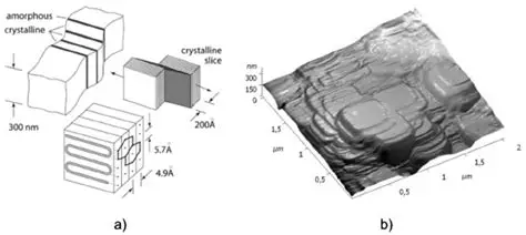
Ceramic fillers, typically fine particles dispersed within the PTFE resin, primarily boost mechanical integrity and thermal properties. By increasing the composite's modulus and hardness, they reduce creep and improve resistance to deformation during soldering or vibration exposure. PTFE PCB ceramic fillers also elevate thermal conductivity, facilitating better heat dissipation in power-dense designs and minimizing hotspots that could alter dielectric behavior. This addition helps match the coefficient of thermal expansion (CTE) more closely with copper cladding, reducing stress at interfaces. While ceramic fillers may slightly elevate the dielectric constant compared to unfilled PTFE, they maintain low dissipation factors essential for high-frequency operation. Engineers must consider filler loading levels to optimize these trade-offs, as excessive amounts can introduce inconsistencies in homogeneity.
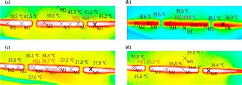
The dispersion quality of ceramic particles profoundly affects overall laminate uniformity. Poor mixing leads to voids or agglomeration, exacerbating signal skew in stripline configurations. Advanced processing techniques ensure even distribution, aligning with IPC-TM-650 test methods for material characterization. In practice, ceramic-filled PTFE variants offer superior z-axis stability, critical for multilayer boards under thermal cycling.
Understanding PTFE PCB Glass Reinforcement
Glass reinforcement, often in the form of woven fabric, provides tensile strength and structural support to the otherwise compliant PTFE matrix. PTFE PCB glass reinforcement transforms soft laminates into rigid panels capable of withstanding fabrication stresses like lamination pressure and drilling. Common styles include E-glass weaves, which enhance abrasion resistance and dimensional control, preventing board bow and twist. This reinforcement is particularly vital for hybrid stackups combining PTFE with other materials. However, the glass weave pattern introduces dielectric anisotropy, potentially causing insertion loss variations at millimeter-wave frequencies due to the glass weave effect. Engineers mitigate this by selecting low-strand-count fabrics or spread-glass constructions for smoother signal paths.
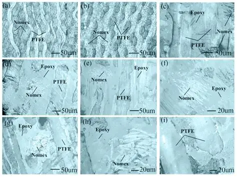
Glass content typically ranges in formulations to balance rigidity with processability. Higher reinforcement density improves mechanical endurance but requires careful surface treatment for adhesion to copper foil. During design, simulation tools model weave-induced impedance deviations to predict performance.
Interplay of Fillers and Reinforcements on PTFE PCB Material Properties
The synergy between PTFE PCB ceramic fillers and PTFE PCB glass reinforcement yields comprehensive enhancements across electrical, thermal, and mechanical domains. Electrically, the combination preserves low loss tangents while stabilizing dielectric constants over frequency and temperature sweeps. Thermally, fillers boost conductivity, complemented by glass's role in constraining expansion mismatches. Mechanically, the duo delivers high flexural strength and low warpage, essential for reliable via formation and assembly.
- Electrical: Ceramic fillers — slight Dk increase with low Df maintained; Glass reinforcement — potential weave effect at high frequencies; Combined — stable impedance control.
- Thermal: Ceramic fillers — higher conductivity and tuned CTE; Glass reinforcement — constrains expansion; Combined — improved reliability through thermal cycles.
- Mechanical: Ceramic fillers — increased modulus and hardness; Glass reinforcement — added tensile strength and rigidity; Combined — reduced warpage and delamination.
This summary illustrates qualitative shifts, guiding material selection per application needs. Adherence to IPC-6012 performance specifications ensures these properties translate to production yields.
Best Practices for Designing and Fabricating Filled PTFE PCBs
Selecting fillers and reinforcements begins with application-specific requirements, such as frequency range and power levels. Engineers should specify filler types for thermal demands and glass styles for mechanical needs, verifying via material datasheets. Fabrication poses challenges due to PTFE's high melt viscosity; sintering processes demand precise temperature ramps to avoid voids. Prepreg bonding requires compatible adhesives, often fluoropolymer-based, to maintain purity. Drilling and plating demand specialized tooling to handle the reinforced structure without fiber pullout. Quality control involves IPC-A-600 visual standards for surface integrity and thermal shock testing.
Post-lamination, bake-out removes absorbed moisture, preventing popcorn effects during reflow. For multilayer builds, sequential lamination controls interlayer alignment. Design rules include wider traces to accommodate CTE differences and ground planes for thermal management.
Key Insights from High-Frequency Applications
In radar phased arrays, ceramic-filled PTFE with glass reinforcement minimizes phase shifts from thermal gradients, ensuring beam accuracy. Troubleshooting warpage often traces to mismatched CTEs, resolved by filler optimization. Engineers report fewer failures in vibration tests with balanced formulations.
Conclusion
Fillers and reinforcements fundamentally elevate PTFE PCB performance, addressing pure resin limitations while preserving high-frequency advantages. PTFE PCB ceramic fillers enhance thermal and mechanical resilience, while PTFE PCB glass reinforcement ensures structural integrity. Understanding these impacts on PTFE PCB material properties empowers engineers to select optimal composites for reliable designs. By integrating best practices and standards guidance, teams achieve superior signal integrity and longevity in advanced electronics.
FAQs
Q1: What are the primary benefits of PTFE PCB ceramic fillers for high-frequency designs?
A1: PTFE PCB ceramic fillers improve mechanical stiffness and thermal conductivity, reducing CTE mismatches with metals. They maintain low dissipation factors suitable for RF applications while enhancing wear resistance during processing. This combination supports stable performance in thermal cycling, aligning with high-speed material specs like IPC-4103.
Q2: How does PTFE PCB glass reinforcement affect dimensional stability?
A2: PTFE PCB glass reinforcement adds rigidity and tensile strength, minimizing board deformation under load or heat. Woven fabrics constrain expansion, crucial for multilayer alignment. However, weave patterns require management to avoid high-frequency skew effects.
Q3: What key PTFE PCB material properties change with fillers and reinforcements?
A3: PTFE PCB material properties shift toward higher modulus, better thermal management, and controlled CTE with ceramic fillers and glass. Electrical traits like low loss remain intact, supporting microwave use. These modifications enhance overall reliability without compromising core advantages.
Q4: How do standards guide the use of filled PTFE laminates?
A4: Standards such as IPC-4101 and IPC-6012 define laminate qualifications, including properties influenced by fillers and reinforcements. They ensure consistency in electrical and mechanical performance for high-frequency PCBs. Compliance aids in qualification for demanding sectors.
References
IPC-4101E - Specification for Base Materials for Rigid and Multilayer Printed Boards. IPC, 2017
IPC-4103D - Specification for Base Materials for High Speed/High Frequency Applications. IPC, 2015
IPC-6012E - Qualification and Performance Specification for Rigid Printed Boards. IPC, 2017
IPC-A-600K - Acceptability of Printed Boards. IPC, 2020





