 ALLPCB


Introduction
In the world of DIY electronics with Arduino, precision is everything. Whether you are mounting sensors, LEDs, or connectors on a custom enclosure, the right holes can make or break your project. Laser drilling offers hobbyists a way to create exact openings without the mess of traditional drills. This technique uses a focused laser beam to vaporize material, resulting in clean edges and tight tolerances. For Arduino enthusiasts, it opens doors to professional-looking laser cut Arduino cases and even experimental custom Arduino boards. This guide walks you through the essentials, from basics to hands-on tips, helping you elevate your projects.
Laser drilling stands out for its speed and repeatability, ideal for prototyping multiple iterations. Hobbyists often struggle with wobbly hand drills or imprecise punches, leading to misalignment in components. With laser methods, you achieve sub-millimeter accuracy, perfect for fitting USB ports or pin headers snugly. As you dive into laser drilling Arduino projects, you will see how it simplifies complex designs like wearable gadgets or IoT nodes.
What Is Laser Drilling and Why It Matters for Arduino Projects
Laser drilling involves directing a high-energy laser beam onto a material surface to remove tiny amounts of matter through ablation. The process creates holes ranging from microns to millimeters, depending on the laser type and settings. Unlike mechanical drilling, it produces no burrs or debris, making it suitable for delicate substrates. In Arduino projects, this translates to flawless mounting holes for shields, precise vents for heat dissipation, or vias in homemade boards.
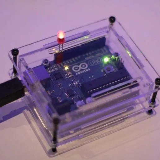
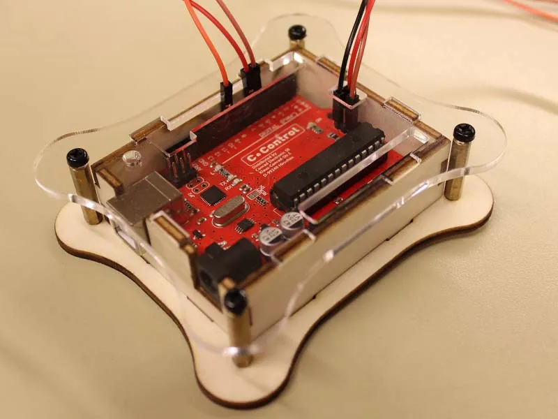
For DIY electronics with Arduino, laser drilling matters because it enables customization at home. Standard enclosures often lack the exact hole patterns needed for your sensors or displays. A laser cut Arduino case, for instance, allows you to design slots for OLED screens or battery compartments with perfect alignment. This precision reduces assembly time and improves reliability, especially in vibration-prone applications like robots.
The technique also supports scalability. Start with a single prototype, then replicate dozens for a maker fair display. It empowers hobbyists to experiment with custom Arduino boards, where microvias connect layers without bulky through-holes. Overall, laser drilling bridges the gap between hobbyist tinkering and professional fabrication.
Technical Principles of Laser Drilling
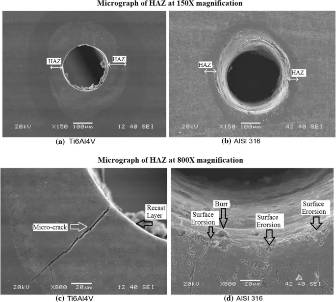
At its core, laser drilling relies on photothermal or photochemical ablation. A laser emits photons that heat the target material to its vaporization point, ejecting particles in a plasma plume. Wavelength selection is key: CO2 lasers at 10.6 micrometers excel on organics like acrylic or wood, while UV lasers around 355 nanometers handle dielectrics in printed circuit boards. Pulse duration controls heat-affected zones; femtosecond pulses minimize thermal damage for ultra-fine features.
Material interaction defines success. Polymers ablate cleanly under moderate power, forming smooth walls. Fiberglass-reinforced epoxies, common in PCBs, require careful energy dosing to avoid charring or delamination. Beam focus, achieved via lenses, determines spot size, often 50-200 microns for hobbyist tools. Multiple passes build depth, with software optimizing paths to prevent taper.
Quality hinges on parameters like repetition rate and assist gas. Nitrogen or air flow clears debris, ensuring roundness. Standards like IPC-A-600K outline acceptability criteria for hole features, such as wall roughness and circularity. Understanding these principles lets you predict outcomes in laser drilling Arduino projects.
Overlapping pulses can widen holes controllably, useful for press-fit components. Scan strategies, like spiral or trepan, influence entry-exit quality. For custom Arduino boards, blind vias stop at specific depths, mimicking high-density interconnect designs per IPC-6012E guidelines.
Practical Solutions and Best Practices for Laser Drilling in Arduino Projects
Start with suitable equipment: a 40-60 watt CO2 laser cutter suits most hobbyist needs for enclosures. Software like LightBurn or Inkscape generates vector files from your Arduino sketches. Design holes oversized by 0.1-0.2 mm to account for beam divergence, ensuring components fit post-expansion. Test on scrap material matching your final substrate, adjusting power from 20-80% and speed from 100-500 mm/s.
Safety comes first: enclose the machine, wear protective eyewear rated for the wavelength, and ventilate fumes. For laser cut Arduino cases, acrylic sheets 3-5 mm thick work well; set multiple passes at low power to avoid melting. Position holes symmetrically around mounting points for stability. Use registration marks for multi-panel alignment, simplifying assembly.
When venturing into custom Arduino boards, mask the copper traces with painter's tape to shield them. Diode or fiber lasers under 10 watts engrave FR4 prototypes, but expect surface carbonization; clean with isopropyl alcohol afterward. Adhere to J-STD-020E for handling sensitivity during post-processing. Prototype iteratively: drill, test fit your Arduino, refine the G-code.
Optimize workflows with bed leveling and auto-focus. For batches, array designs save time. Post-drill inspection with calipers confirms tolerances under 0.05 mm. These practices ensure reliable laser drilling Arduino projects.
Troubleshooting Common Issues in Laser Drilling
Misaligned holes often stem from loose fixturing; secure workpieces with magnets or vacuum tables. Tapered holes result from defocus; recalibrate Z-axis before runs. Excessive heat causes cracking in plastics; reduce pulse energy or add cooling intervals.
Charring on PCBs indicates overpowering; drop to 30% and increase passes. Incomplete penetration needs higher repetition rates. For stubborn debris, integrate air assist at 10-20 psi. Log parameters in a spreadsheet for each material, speeding future fixes.
In custom Arduino boards, via shorts arise from residue; ultrasonic clean in solvent. If holes ovalize, check belt tension on gantry systems. These steps keep your DIY electronics with Arduino on track.
Conclusion
Laser drilling transforms Arduino projects by delivering unmatched precision for holes in cases and boards. From understanding ablation principles to mastering settings, hobbyists gain tools for professional results. Apply best practices, reference standards like IPC-A-600K, and troubleshoot proactively for success. Whether crafting a laser cut Arduino case or prototyping custom Arduino boards, this method boosts creativity and reliability. Experiment confidently, and watch your DIY electronics with Arduino shine.
FAQs
Q1: What laser types work best for laser drilling Arduino projects?
A1: CO2 lasers handle enclosures like acrylic cases effectively, while UV or fiber lasers suit PCB prototypes. Choose based on material: 40W CO2 for hobbyist laser cut Arduino cases, diode for light engraving on custom Arduino boards. Always match power to thickness, starting low to test. Safety gear and ventilation are essential for clean results.
Q2: How do I design hole patterns for DIY electronics with Arduino using laser drilling?
A2: Use vector software to place holes precisely over component footprints from datasheets. Add 0.1 mm clearance for thermal expansion. Array tests on scrap for laser drilling Arduino projects. Ensure symmetry for balance in enclosures. Calibrate after design to meet tolerances.
Q3: Can hobbyists laser drill custom Arduino boards at home?
A3: Yes, with diode or low-power fiber lasers, but expect surface effects on FR4. Mask traces, use multiple passes, and clean thoroughly. It excels for prototypes in DIY electronics with Arduino, not production. Follow IPC guidelines for feature quality. Avoid high heat to prevent delamination.
Q4: What safety precautions apply to laser drilling Arduino projects?
A4: Enclose the laser, use wavelength-specific goggles, and vent fumes outdoors. Secure materials to prevent movement. Fire watch for flammables like acrylic. Ground equipment to avoid shocks. These ensure safe laser cut Arduino case fabrication.
References
IPC-A-600K — Acceptability of Printed Boards. IPC, 2020
IPC-6012E — Qualification and Performance Specification for Rigid Printed Boards. IPC, 2017
J-STD-020E — Moisture/Reflow Sensitivity Classification. JEDEC, 2014


