 ALLPCB


Component substitution plays a central role in maintaining production schedules and extending the service life of electronic assemblies. Engineers frequently encounter situations where original parts become unavailable due to manufacturer discontinuations or supply chain disruptions. Effective PCB component substitution requires systematic comparison of electrical, mechanical, and thermal parameters to ensure the replacement maintains overall system performance. Cross-referencing components involves reviewing manufacturer datasheets side by side while verifying compatibility with existing board layouts. This structured approach reduces the risk of functional failures after replacement.
Why Finding Equivalent Parts Matters for Electric Engineers
Procurement teams and design engineers must address obsolete components promptly to avoid costly redesigns or production halts. Replacing obsolete components through careful sourcing of alternative electronic parts preserves the original circuit behavior without introducing new failure modes. When substitution is handled correctly, projects stay on schedule and maintain compliance with performance specifications. Engineers rely on documented parameter matching to confirm that the new part delivers equivalent voltage ratings, current handling, and switching speeds. This practice also supports long-term maintainability of deployed equipment across multiple production batches.
Technical Principles of Cross-Referencing Components
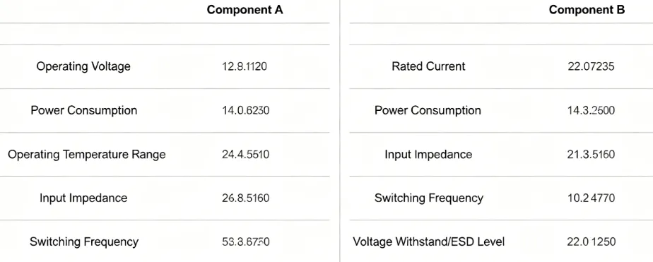
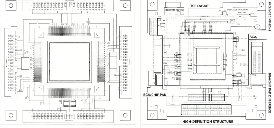
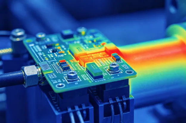
Successful identification of equivalents begins with a detailed review of key electrical characteristics listed in component datasheets. Parameters such as forward voltage drop, leakage current, and frequency response must align within acceptable tolerances for the specific circuit application. Mechanical dimensions, including package size and lead pitch, require verification to ensure the substitute fits existing footprints without layout changes. Thermal characteristics, such as junction-to-ambient resistance and maximum operating temperature, influence heat dissipation and long-term reliability under load. Environmental factors including moisture sensitivity and soldering profile compatibility further determine whether a candidate part can be integrated without additional process adjustments.
Industry standards guide the qualification process during component evaluation. Engineers often reference IPC specifications when assessing board-level interactions after substitution. Parameter drift over temperature and voltage must remain within limits established during original design validation. Logical comparison matrices help organize data from multiple datasheets, highlighting any deviations that could affect circuit stability. This methodical evaluation prevents subtle mismatches that might only appear during extended operation or environmental stress testing.
Related Reading: Supercapacitors as Battery Replacements in Embedded Systems
Best Practices for PCB Component Substitution
Begin the substitution process by creating a comprehensive list of critical specifications derived from the original part and the surrounding circuitry. Next, search distributor databases and manufacturer resources for candidates that meet or exceed those specifications. Verify package outlines and pad layouts against the existing PCB artwork to confirm physical interchangeability. Perform electrical simulations or breadboard tests to validate signal integrity and power delivery before committing to production quantities. Document every comparison step to support future audits or additional substitutions.
Standards such as those from JEDEC provide guidance on handling moisture-sensitive devices during the transition to alternative parts. Engineers should confirm that the substitute maintains the same moisture sensitivity level to avoid reflow-related damage. After initial selection, prototype assemblies undergo functional testing under representative operating conditions. Any observed deviations in timing, noise margins, or efficiency trigger further refinement of the candidate list. This iterative validation ensures the final choice delivers consistent performance across temperature and voltage ranges.
Practical Steps for Sourcing Alternative Electronic Parts
Start by extracting all relevant part numbers and specifications from the bill of materials and associated schematics. Use parametric search tools available through authorized distributors to filter candidates by voltage, current, package type, and tolerance. Cross-check manufacturer change notifications to identify any recent process or material updates that could affect performance. Request samples for laboratory evaluation when datasheet data alone leaves uncertainty about critical parameters. Once samples arrive, measure actual performance against original specifications using calibrated test equipment.
Final qualification includes environmental stress testing to confirm reliability under expected operating conditions. Engineers record all test results in a substitution report that includes acceptance criteria and any required derating factors. This documentation supports traceability and simplifies future maintenance activities. When multiple candidates satisfy the requirements, preference is given to parts with longer projected availability to minimize repeat substitution efforts.
Related Reading: PCB Rework Station for Beginners: A Simple Guide to Component Replacement
Conclusion
Systematic identification of equivalent components ensures continued production and reliable operation of electronic assemblies. By focusing on electrical, mechanical, and thermal parameter alignment, engineers achieve successful PCB component substitution without compromising design intent. Structured comparison methods combined with adherence to established industry practices reduce risk and support long-term product supportability. Consistent application of these techniques allows teams to respond effectively to component obsolescence while maintaining quality and performance standards.
FAQs
Q1: How does PCB component substitution differ from simple part replacement?
A1: PCB component substitution involves detailed cross-referencing of electrical, mechanical, and thermal specifications to ensure the alternative part maintains original circuit performance. Engineers compare datasheets, verify footprint compatibility, and conduct validation testing before approving the change. This process differs from direct replacement because it accounts for potential variations in characteristics that could affect system behavior.
Q2: What steps help when finding equivalent parts for obsolete components?
A2: The process starts with extracting critical parameters from the original datasheet and surrounding circuit requirements. Engineers then search for candidates using parametric filters and verify physical dimensions against existing board layouts. Functional testing on prototypes confirms that the substitute meets performance targets under operating conditions.
Q3: Why is cross-referencing components important during sourcing of alternative electronic parts?
A3: Cross-referencing components ensures that selected alternatives match key specifications such as voltage ratings, current capacity, and package outlines. This verification reduces the likelihood of introducing new failure modes or requiring board redesigns. Proper cross-referencing also supports compliance with qualification requirements during production transitions.
Q4: How do industry standards support replacing obsolete components on PCBs?
A4: Standards provide consistent criteria for evaluating moisture sensitivity, soldering profiles, and board-level qualification after substitution. Engineers apply these guidelines to confirm that alternative parts integrate reliably without process changes. Following recognized standards helps maintain overall assembly quality and long-term reliability.
References
IPC-6012E — Qualification and Performance Specification for Rigid Printed Boards. IPC, 2017
JEDEC J-STD-020E — Moisture/Reflow Sensitivity Classification. JEDEC, 2014
IPC-A-600K — Acceptability of Printed Boards. IPC, 2020


