 ALLPCB


Introduction
FR-4 stands as the cornerstone material in printed circuit board fabrication, offering a balance of electrical insulation, mechanical strength, and cost-effectiveness that suits a wide range of electronic applications. Electric engineers rely on its predictable performance to ensure signal integrity, thermal management, and long-term reliability in designs from consumer devices to industrial controls. Key properties such as the FR-4 PCB dielectric constant, FR-4 PCB thermal conductivity, FR-4 PCB glass transition temperature, FR-4 PCB moisture absorption, and FR-4 PCB flame retardancy directly influence PCB performance under operating conditions. Variations in these properties arise from resin formulations, glass weave styles, and processing parameters, making a fundamental understanding essential for informed material selection. This article delves into these fundamentals, providing engineers with structured insights grounded in industry practices. By examining each property's engineering principles and implications, designers can optimize PCB layouts and stackups for specific requirements.
What Is FR-4 and Why It Matters in PCB Design
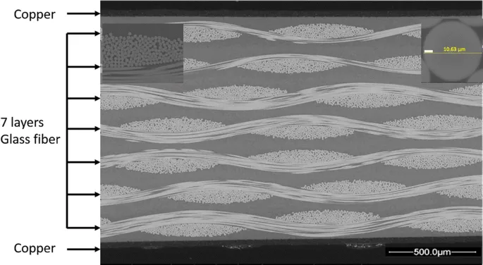
FR-4 is a composite laminate consisting of woven fiberglass cloth impregnated with a flame-retardant epoxy resin, designated as grade 4 in the NEMA flame retardancy classification system. This material's designation reflects its self-extinguishing characteristics, which prevent fire propagation in electronic assemblies. In PCB design, FR-4 serves as the primary substrate due to its high strength-to-weight ratio, dimensional stability, and compatibility with standard fabrication processes like multilayer lamination and copper etching. Engineers value FR-4 for its versatility across frequencies and temperatures, though its properties must align with application demands to avoid issues like signal loss or delamination. Specifications for FR-4 laminates are outlined in IPC-4101, which defines grades based on performance criteria including electrical and thermal attributes. Understanding these fundamentals enables engineers to predict behavior in high-density interconnects or power electronics.
The relevance of FR-4 properties extends to signal propagation, where impedance control hinges on dielectric consistency, and thermal cycling, where material stability prevents warpage. For electric engineers, selecting FR-4 involves balancing cost with performance margins, especially in environments with varying humidity or heat loads. Poor material choice can lead to failures like cafing or solder joint cracks, underscoring the need for precise property knowledge.
FR-4 PCB Dielectric Constant: Electrical Performance Foundation
The FR-4 PCB dielectric constant, often denoted as Dk or relative permittivity, quantifies the material's ability to store electrical energy in an electric field, typically measured between 3.8 and 4.8 at 1 MHz depending on resin content and glass weave. This value decreases slightly with increasing frequency due to polarization mechanisms in the epoxy matrix, affecting microstrip and stripline impedance calculations. Engineers must account for Dk variation across the board, as glass fiber orientation creates anisotropy, with in-plane values differing from through-plane by up to 20%. In high-speed designs, a stable Dk ensures controlled propagation delay and minimizes crosstalk, while inconsistencies can degrade eye diagrams. Test methods like IPC-TM-650 2.5.5.5 provide standardized measurement protocols for consistency.
Practical implications include stackup planning, where copper thickness and core/prepreg combinations influence effective Dk. For RF applications, engineers select tighter weave styles to reduce Dk spread, enhancing phase matching in differential pairs. Moisture ingress further elevates Dk, amplifying losses, so preconditioning becomes critical in humid environments.
FR-4 PCB Thermal Conductivity: Heat Dissipation Challenges
FR-4 PCB thermal conductivity measures the material's capacity to conduct heat, typically ranging from 0.25 to 0.3 W/mK in the through-plane direction, significantly lower than copper's 400 W/mK. This low value stems from the epoxy resin's insulating nature dominating over the glass fibers' moderate conductivity, creating thermal bottlenecks in multilayer boards. In-plane conductivity reaches about 0.5 to 1 W/mK due to fiber alignment, but overall, FR-4 relies on copper planes and vias for primary heat spreading. Engineers address this by incorporating thermal vias and thicker copper, especially in power-dense designs where junction temperatures must stay below 125°C. Junction-to-ambient thermal resistance rises exponentially without mitigation, risking component degradation.
Design strategies focus on spreading heat laterally via ground planes while minimizing stackup thickness to shorten through-plane paths. Finite element simulations help predict hotspots, guiding via placement under high-power ICs. For high-reliability applications, combining FR-4 with metal-core alternatives hybridizes thermal paths without sacrificing electrical isolation.
FR-4 PCB Glass Transition Temperature: Thermal Reliability Threshold
The FR-4 PCB glass transition temperature, or Tg, marks the point where the epoxy resin shifts from a glassy, rigid state to a rubbery one, usually around 130 to 140°C for standard grades. Above Tg, the coefficient of thermal expansion (CTE) increases dramatically from about 15 ppm/°C below Tg to over 50 ppm/°C, potentially causing via barrel cracks or pad lifts during reflow soldering. IPC-TM-650 2.4.24 outlines dynamic mechanical analysis (DMA) for precise Tg determination, essential for lead-free processes peaking at 260°C. Higher Tg variants (150°C+) offer margins for automotive or aerospace use, reducing z-axis expansion mismatch with copper. Engineers specify Tg based on peak exposure, ensuring multiple reflow cycles without degradation.
Warpage becomes pronounced post-Tg due to asymmetric CTE, exacerbated in thin cores or large panels. Mitigation involves balanced copper distribution and sequential lamination, with bow and twist limited per IPC-6012 criteria. Reliability testing via thermal cycling accelerates failure modes, validating material choice.
FR-4 PCB Moisture Absorption: Reliability Risk Factor
FR-4 PCB moisture absorption, typically 0.1 to 0.3% by weight after 24-hour immersion at 23°C, occurs via capillary action in glass weave interstices and resin diffusion. Absorbed water lowers surface insulation resistance, increases Dk by up to 10%, and reduces Tg, promoting popcorn cracking during reflow vaporization. JEDEC J-STD-020 classifies handling based on moisture sensitivity levels, mandating dry baking at 125°C for 24 hours prior to soldering. Engineers monitor absorption through weight gain tests, correlating it to ionic contamination risks in humid storage. Conformal coatings or edge sealing further protect assemblies in outdoor or washable environments.
Desorption kinetics follow Fick's law, with equilibrium reached in weeks at 85% RH, emphasizing sealed packaging. In high-voltage designs, absorbed moisture triggers dendritic growth, shortening lifespan. Preconditioning protocols ensure consistency across supply chains.
FR-4 PCB Flame Retardancy: Safety Imperative
FR-4 PCB flame retardancy derives from brominated epoxy resins releasing halogen radicals to interrupt combustion chains, achieving vertical burn ratings that self-extinguish within seconds. This property prevents flame spread in overcrowded assemblies, complying with safety mandates for enclosed electronics. During UL94 vertical testing, FR-4 grades exhibit no dripping or afterglow beyond 10 seconds, critical for multilayer integrity. Engineers prioritize this in power supplies or telecom gear, where fault currents could ignite. Resin formulations balance retardancy with processability, avoiding voids from volatile halogens.
Over-reliance on halogens raises environmental concerns, prompting low-halogen alternatives with comparable performance. Testing verifies retardancy post-lamination, as processing can alter char formation.
Best Practices for FR-4 in Electrical Engineering Designs
Select FR-4 grades per application: standard Tg for cost-sensitive boards, high Tg for thermal extremes. Verify supplier data sheets against IPC-4101 conformance for Dk uniformity and low moisture specs. Incorporate thermal relief vias and ground pours to compensate for modest conductivity, simulating junction temperatures early. Bake boards at 125°C for 4-8 hours before reflow if storage exceeds 168 hours at 40°C/90% RH. Balance copper weight across layers to minimize Tg-induced warpage, targeting less than 0.75% bow/twist. For high-frequency signals, use low-loss prepregs with tighter Dk control.
Conclusion
Mastering FR-4 PCB material properties empowers electric engineers to design robust, reliable circuits tailored to electrical and environmental demands. The interplay of dielectric constant, thermal conductivity, glass transition temperature, moisture absorption, and flame retardancy dictates performance limits, from signal fidelity to safety compliance. By referencing standards like IPC-4101 and applying best practices, designs achieve optimal margins without over-specification. Future trends may shift to advanced laminates, but FR-4 remains foundational due to its proven versatility. Engineers should prioritize material qualification testing to bridge datasheets with real-world behavior.
FAQs
Q1: What is the typical FR-4 PCB dielectric constant range for high-speed designs?
A1: The FR-4 PCB dielectric constant typically spans 3.8 to 4.8 at 1 MHz, narrowing to 4.0-4.5 at gigahertz frequencies due to reduced dipole polarization. Engineers calculate effective Dk considering glass weave and resin ratio for accurate impedance control in microstrips. Variations under 0.5 spread suit most applications, with testing per IPC methods ensuring consistency across panels.
Q2: How does FR-4 PCB thermal conductivity impact power electronics?
A2: FR-4 PCB thermal conductivity, around 0.25-0.3 W/mK through-plane, necessitates copper planes and vias for heat spreading in power designs. Low values elevate thermal resistance, requiring simulations to keep hotspots below component limits. Hybrid approaches with thicker copper mitigate risks in high-current paths.
Q3: Why is FR-4 PCB glass transition temperature critical during assembly?
A3: FR-4 PCB glass transition temperature, often 130-140°C for standard grades, defines the threshold where CTE surges, risking delamination in reflow peaks over 250°C. Higher Tg variants provide margins for lead-free soldering. DMA testing per IPC-TM-650 verifies suitability for multiple thermal excursions.
Q4: What are the effects of FR-4 PCB moisture absorption on reliability?
A4: FR-4 PCB moisture absorption of 0.1-0.3% elevates Dk, lowers SIR, and induces steam pressure cracks during soldering. Pre-baking per JEDEC guidelines desorbs water, preserving integrity. Storage in dry nitrogen bags prevents uptake in humid climates.
References
IPC-4101E — Specification for Base Materials for Rigid and Multilayer Printed Boards. IPC, 2017
IPC-TM-650 — Test Methods Manual. IPC, latest revision
JEDEC J-STD-020E — Moisture/Reflow Sensitivity Classification for Nonhermetic Surface Mount Devices. JEDEC, 2014


