 ALLPCB


Essential Guide to Passive Components for Electronics Hobbyists
Passive components form the foundation of nearly every electronic circuit that an electronics hobbyist builds. These parts do not generate or amplify signals but instead control current, store energy, and filter signals in predictable ways. For anyone starting out with breadboard circuits, understanding resistors and capacitors is essential before moving on to more complex assemblies. Proper selection and handling of these basic components help ensure reliable performance and safe experimentation on the workbench.
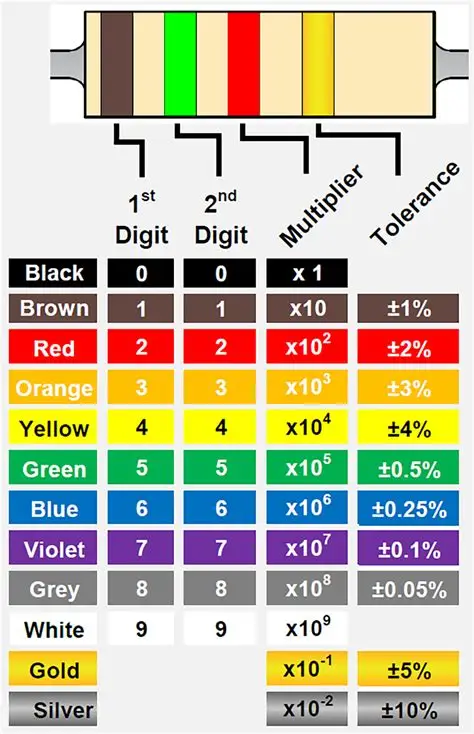
Understanding Resistors and Reading Color Codes
Resistors limit current flow and divide voltages within a circuit. They come in several physical forms, including carbon film, metal film, and wire-wound types, each offering different tolerance and power-handling characteristics. Hobbyists most often encounter axial-lead resistors because they insert easily into breadboards and solder quickly to stripboard or perfboard. Color bands on the resistor body indicate resistance value and tolerance according to a standardized coding system that remains consistent across manufacturers. Learning to read resistor color codes quickly saves time when sorting through component kits or verifying values during troubleshooting.
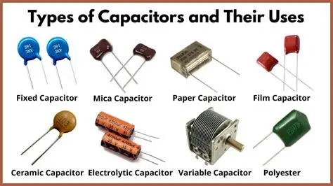
Choosing the Right Capacitors for Your Project
Capacitors store and release electrical energy and appear in many circuit roles such as coupling, decoupling, timing, and filtering. Common types include ceramic, electrolytic, film, and tantalum capacitors. Ceramic capacitors suit high-frequency applications and offer small size with good stability, while electrolytic capacitors provide higher capacitance values needed for power supply smoothing. Hobbyists must observe polarity markings on electrolytic types to avoid damage during circuit testing. Selecting the correct capacitor type depends on voltage rating, capacitance value, and the frequency range of the intended circuit.
Best Practices for Breadboard Circuit Prototyping
Breadboard circuits allow rapid prototyping without permanent soldering. When placing resistors and capacitors on a solderless breadboard, keep lead lengths short to minimize unwanted inductance and resistance. Arrange components so that power rails run along the edges and signal paths stay organized to reduce crosstalk. Always double-check connections against the schematic before applying power, because a misplaced resistor or reversed capacitor can prevent the circuit from functioning or cause component failure.
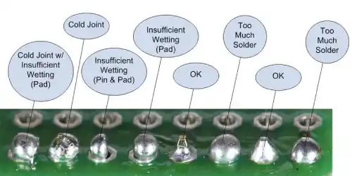
Mastering Professional Soldering Techniques
Soldering techniques become necessary once a design moves from breadboard to a more permanent board. Begin by cleaning component leads and the board surface to ensure good solder wetting. Apply heat to both the lead and the pad simultaneously, then feed solder into the joint until it flows smoothly around the connection. Allow the joint to cool undisturbed to form a strong mechanical and electrical bond. Following established industry practices helps produce consistent, reliable solder joints even on first projects.
Industry Standards: IPC Guidelines for Hobbyists
Industry guidelines such as those in IPC J-STD-001 emphasize proper process control and inspection criteria for soldered electrical assemblies, which hobbyists can apply at a basic level to improve joint quality. Another relevant document, J-STD-075, provides classification guidance for passive components during assembly processes and helps users understand handling considerations that affect long-term reliability.
Practical Tips for Component Management and Troubleshooting
Practical best practices include always verifying component values with a multimeter before installation, using the lowest effective wattage or voltage rating that meets circuit needs, and storing parts in labeled containers to avoid mix-ups. When working with breadboard circuits, keep a small stock of common resistor values from 100 ohms to 1 megohm and capacitor values from 10 picofarads to 1000 microfarads. These ranges cover most beginner projects involving LEDs, simple timers, and audio filters.
Troubleshooting often starts with visual inspection of solder joints and component orientation. If a circuit fails to operate, measure voltages at key nodes and compare them against expected values calculated from resistor and capacitor networks. Heat damage from prolonged soldering iron contact can alter resistor values or dry out electrolytic capacitors, so limit heat exposure to a few seconds per joint.
Conclusion
Mastering basic components gives electronics hobbyists the confidence to move from simple breadboard experiments to more permanent soldered projects. Resistor color codes and capacitor type selection become second nature with practice, while careful soldering techniques ensure durable results. Consistent attention to these fundamentals supports successful learning and project completion over time.
FAQs
Q1: What resistor color code knowledge does every electronics hobbyist need for reading component values quickly?
A1: Familiarity with the standard four-band or five-band color system allows rapid identification of resistance and tolerance without a meter. This skill proves especially useful when sorting through mixed kits during breadboard circuit assembly.
Q2: Which capacitor types are most suitable for beginner breadboard circuits involving timing or filtering?
A2: Ceramic capacitors work well for high-frequency decoupling and timing, while electrolytic types handle larger capacitance needs in power supply sections. Observing polarity on electrolytic capacitors prevents damage during initial testing.
Q3: How do proper soldering techniques improve the reliability of circuits built with basic components?
A3: Clean joints formed by applying heat evenly to leads and pads create strong electrical connections that withstand vibration and thermal cycling. Following recognized process guidelines reduces the chance of cold joints or component overheating.
Q4: What steps help avoid common mistakes when placing resistors and capacitors on a breadboard?
A4: Organize components by value, verify each part with a meter, and maintain short lead lengths to limit parasitic effects. Double-checking the layout against the schematic before powering the circuit prevents most simple errors.
References
IPC J-STD-001 — Requirements for Soldered Electrical and Electronic Assemblies. IPC.
J-STD-075 — Classification of Passive and Solid State Devices for Assembly Processes. IPC and ECIA.
IPC-A-610 — Acceptability of Electronic Assemblies. IPC.


