 ALLPCB


Introduction
Rigid printed circuit boards form the backbone of many electronic systems in demanding applications such as automotive controls, industrial machinery, and outdoor equipment. These boards face constant threats from moisture, dust, chemicals, temperature fluctuations, and mechanical stress, which can lead to corrosion, short circuits, or outright failure. Conformal coating emerges as a critical solution by applying a thin, protective polymeric film that conforms to the contours of the board and its components. This coating enhances reliability without significantly adding weight or volume, making it ideal for rigid boards where space and performance are paramount. For electrical engineers designing or specifying PCBs, understanding conformal coating ensures optimal environmental protection for PCBs in real-world deployments. Key aspects include selecting conformal coating types, mastering applying conformal coating techniques, controlling conformal coating thickness, and knowing conformal coating removal methods for rework.
What Is Conformal Coating and Why It Matters for Rigid Boards
Conformal coating is a dielectric layer, typically 25 to 250 microns thick, applied to the surface of a printed circuit board to shield it from harmful environmental factors. On rigid boards, which consist of solid fiberglass-reinforced epoxy substrates, this coating prevents ionic contamination, fungal growth, and electrical arcing under high humidity. Unlike flexible circuits, rigid boards benefit from coatings that maintain structural integrity during thermal cycling and vibration, common in sectors like power electronics and telecommunications. The relevance stems from the increasing complexity of modern rigid PCBs, with finer pitches and higher component densities that amplify vulnerability to environmental ingress. Without proper protection, even minor exposure to salt spray or solvents can degrade solder joints and traces over time. Thus, conformal coating directly contributes to extending service life and meeting reliability targets in harsh conditions.
Conformal Coating Types: Selecting the Right Material
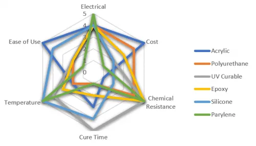
Conformal coating types vary in chemistry to address specific threats, with five primary categories dominating industry use: acrylic, silicone, urethane, epoxy, and parylene. Acrylic coatings excel in moisture resistance and ease of removal, making them suitable for general-purpose rigid boards in consumer electronics. Silicone types offer superior flexibility and wide temperature tolerance, from -65°C to 200°C, ideal for automotive engine controls exposed to thermal extremes. Urethane coatings provide robust abrasion resistance and humidity protection, often chosen for industrial rigid PCBs handling mechanical wear. Epoxy formulations deliver excellent chemical resistance against solvents and fuels, though they are harder to remove, suiting harsh chemical environments. Parylene, applied via vapor deposition, forms a pinhole-free barrier with exceptional uniformity, perfect for medical or aerospace rigid boards requiring ultra-thin, conformal coverage.
Each type undergoes qualification testing per IPC-CC-830C, which evaluates dielectric strength, thermal shock, and moisture insulation. Engineers must match the coating to the application's dominant stressors, such as high humidity favoring silicones or aggressive chemicals needing epoxies. Factory processes prioritize solvent-based or 100% solids formulations to minimize voids during application on rigid substrates.
Mechanisms of Environmental Protection for PCBs
Conformal coating safeguards rigid PCBs by creating a hydrophobic barrier that repels water and prevents electrochemical migration between conductors. This is crucial in high-humidity settings where uncapped boards suffer dendritic growth, leading to intermittent failures. The coating also blocks particulate ingress, such as dust or salt aerosols, which accelerate corrosion on exposed copper traces and terminations. Thermal management improves as the film dissipates heat evenly while insulating against rapid coefficient of thermal expansion mismatches during cycling. Chemical resistance stems from the polymer's inertness, shielding solder masks and components from oils, cleaners, and pollutants common in industrial use. Vibration damping occurs through the coating's elasticity, reducing fatigue in lead wires and surface-mount parts on rigid boards.
In practice, these mechanisms align with IPC-A-610 criteria for assembly acceptability, ensuring no defects like bubbles or dewetting compromise protection. Engineers verify performance through accelerated life testing, simulating years of exposure in weeks.
Applying Conformal Coating: Processes and Best Practices
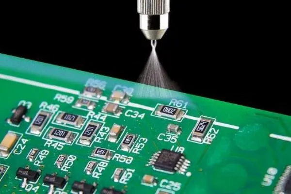
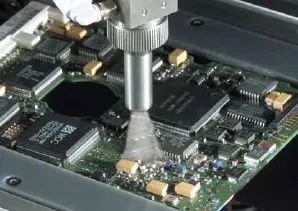
Applying conformal coating to rigid boards begins with meticulous surface preparation to ensure adhesion and uniformity. Engineers clean boards using isopropyl alcohol or plasma treatment to remove fluxes and oxides, followed by masking connectors, fiducials, and test points with tape or fixtures. Common methods include selective spraying for precision on high-density boards, dip coating for full coverage on simpler layouts, and brushing for repairs. High-volume low-pressure (HVLP) spraying minimizes overspray while achieving consistent wet film thickness, typically targeting 50 to 100 microns before curing. Vapor deposition for parylene suits complex geometries but requires vacuum chambers. Post-application, controlled curing via air dry, UV, or heat ovens prevents cracking, with bake times varying by type.
Best practices emphasize automation in production lines for repeatability, using robotic sprayers to coat both sides uniformly. Ventilation and PPE address solvent vapors, while edge bead removal via scraping avoids pooling that could trap contaminants.
Conformal Coating Thickness: Critical Specifications
Conformal coating thickness directly influences protection levels, flexibility, and rework feasibility, with typical dry film values ranging from 25 to 127 microns per side. Thinner layers, around 25 to 50 microns, suffice for mild environments, preserving board flexibility and reducing stress on components during thermal expansion. Thicker applications, up to 200 microns, enhance durability in severe conditions but risk cracking if exceeding material limits. Uniformity is paramount; variations over 50% lead to pinholes or bridging, per inspection standards. Measurement techniques include micrometers for bulk checks, eddy current gauges for non-contact verification, and cross-section microscopy for validation.
Engineers specify thickness based on IPC-CC-830C performance classes, balancing dielectric breakdown voltage against mechanical strain. Over-application increases costs and capacitance, while under-coating fails prematurely.
- Acrylic — Recommended dry thickness: 25-75 microns — Key notes: Easy spray, fast cure
- Silicone — Recommended dry thickness: 50-125 microns — Key notes: Flexible, high temp
- Urethane — Recommended dry thickness: 35-100 microns — Key notes: Abrasion resistant
- Epoxy — Recommended dry thickness: 50-150 microns — Key notes: Chemical barrier
- Parylene — Recommended dry thickness: 12-50 microns — Key notes: Uniform vapor dep.
Conformal Coating Removal: Techniques for Rework
Conformal coating removal becomes necessary during repairs, failures analysis, or upgrades on rigid boards. Solvent stripping uses type-specific chemistries, such as methylene chloride for acrylics or toluene for silicones, applied via soaking or wiping with ultrasonics for efficiency. Abrasive methods like microblasting with baking soda media remove thicker films without damaging traces, ideal for urethanes. Thermal techniques involve localized heating to 150-200°C to soften and peel the coating, followed by scraping. Plasma ashing offers dry, residue-free removal for epoxies, etching the polymer selectively.
IPC-7711/7721 outlines these procedures, classifying methods by substrate impact and thickness. Post-removal, boards require cleaning and inspection to restore integrity. Engineers prioritize minimal aggression to avoid delamination in rigid multilayers.
Standards and Quality Assurance in Conformal Coating
Adherence to industry standards ensures conformal coatings perform reliably on rigid boards. IPC-CC-830C defines qualification tests like dielectric withstand, insulation resistance after humidity, and fluorescence under black light for thickness gauging. IPC-A-610 provides visual criteria, rejecting voids larger than 10% of adjacent areas or fish eyes indicating contamination. For assemblies, J-STD-001 mandates coating coverage over 75% of solder fillets without bridging. Factory quality control incorporates automated optical inspection (AOI) post-cure, verifying uniformity across panels. These protocols minimize field failures, aligning with ISO 9001 quality systems for process repeatability.
Conclusion
Conformal coating stands as an essential shield for rigid boards against environmental assaults, with types tailored to specific needs and application methods ensuring precision. Controlling thickness and mastering removal techniques further optimize lifecycle management. Electrical engineers benefit from these practices to deliver robust designs that withstand real-world rigors. By integrating standards like IPC-CC-830C, production achieves consistent environmental protection for PCBs, reducing downtime and costs. Prioritizing these elements elevates PCB reliability in critical applications.
FAQs
Q1: What are the main conformal coating types for rigid boards?
A1: The primary conformal coating types include acrylic for moisture protection, silicone for temperature extremes, urethane for abrasion resistance, epoxy for chemical durability, and parylene for pinhole-free coverage. Selection depends on environmental factors like humidity or solvents. Per IPC-CC-830C, each undergoes testing for dielectric and mechanical properties. These types conform well to rigid substrates without adding bulk.
Q2: How should you go about applying conformal coating to achieve optimal results?
A2: Applying conformal coating starts with cleaning and masking, followed by spraying, dipping, or vapor deposition for uniform coverage. Target wet film to yield 25-127 microns dry thickness, then cure per material specs. Use HVLP for precision on dense rigid boards. Inspection per IPC-A-610 ensures no defects like bubbles.
Q3: What is the typical conformal coating thickness and why does it matter?
A3: Typical conformal coating thickness ranges from 25 to 127 microns dry film, balancing protection against flexibility. Thinner suits mild environments; thicker handles harsh ones. Excess causes stress cracks; insufficient allows ingress. Measure with gauges and verify against IPC standards for reliability.
Q4: What methods are used for conformal coating removal during rework?
A4: Conformal coating removal employs solvents, abrasion, thermal softening, or plasma, per IPC-7711/7721 guidelines. Match method to type and thickness to minimize board damage. Clean residues post-removal and inspect for integrity. This enables efficient repairs on rigid PCBs.
References
IPC-CC-830C — Qualification and Performance Specification for Conformal Coating Materials. IPC.
IPC-A-610H — Acceptability of Electronic Assemblies. IPC.
IPC-7711/7721B — Rework, Modification and Repair of Electronic Assemblies. IPC.
IPC-6012E — Qualification and Performance Specification for Rigid Printed Boards. IPC, 2017


