 ALLPCB


Introduction
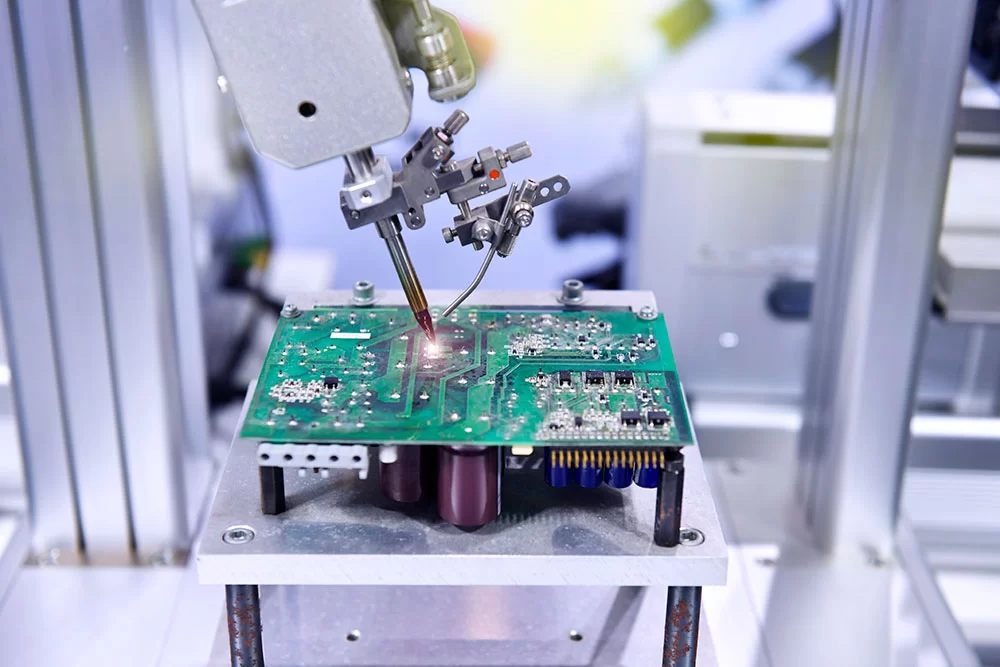
Surface finish selection plays a pivotal role in successful SMT assembly, particularly when dealing with high-density boards. The SMT assembly finish ensures reliable solder joint formation, protects exposed copper from oxidation, and maintains pad coplanarity during reflow processes. Engineers often face challenges with fine-pitch components PCB, where uneven finishes can lead to soldering defects like bridging or incomplete wetting. Common options such as ENIG for SMT and OSP reflow soldering must align with solder paste compatibility to avoid issues in production. This practical guide breaks down key considerations, helping you match finishes to assembly needs while adhering to proven engineering practices. By understanding these factors, you can minimize rework and enhance yield rates.
Understanding PCB Surface Finishes and Their Role in SMT Assembly
PCB surface finish refers to the thin metallic or organic coating applied to exposed copper pads and traces after fabrication. This layer prevents corrosion, promotes solder wetting, and provides a stable platform for component leads during SMT processes. In SMT assembly, the finish must withstand multiple thermal cycles, including reflow soldering, without degrading solder paste compatibility. Poor finish choice can result in tombstoning, voids, or delamination, especially on fine-pitch components PCB where tolerances are tight. Industry standards like IPC-A-600K outline acceptability criteria for these finishes, ensuring they meet performance requirements for Class 2 and Class 3 assemblies.
The relevance intensifies with modern electronics demanding higher I/O counts and smaller pitches, often below 0.5mm. Finishes influence not just initial solderability but also long-term reliability under vibration, humidity, or thermal stress. For instance, a non-planar finish exacerbates stencil printing inconsistencies, leading to uneven solder paste deposition. Selecting the right SMT assembly finish balances cost, shelf life, and process window, directly impacting assembly throughput.
Key Types of Surface Finishes for SMT Applications
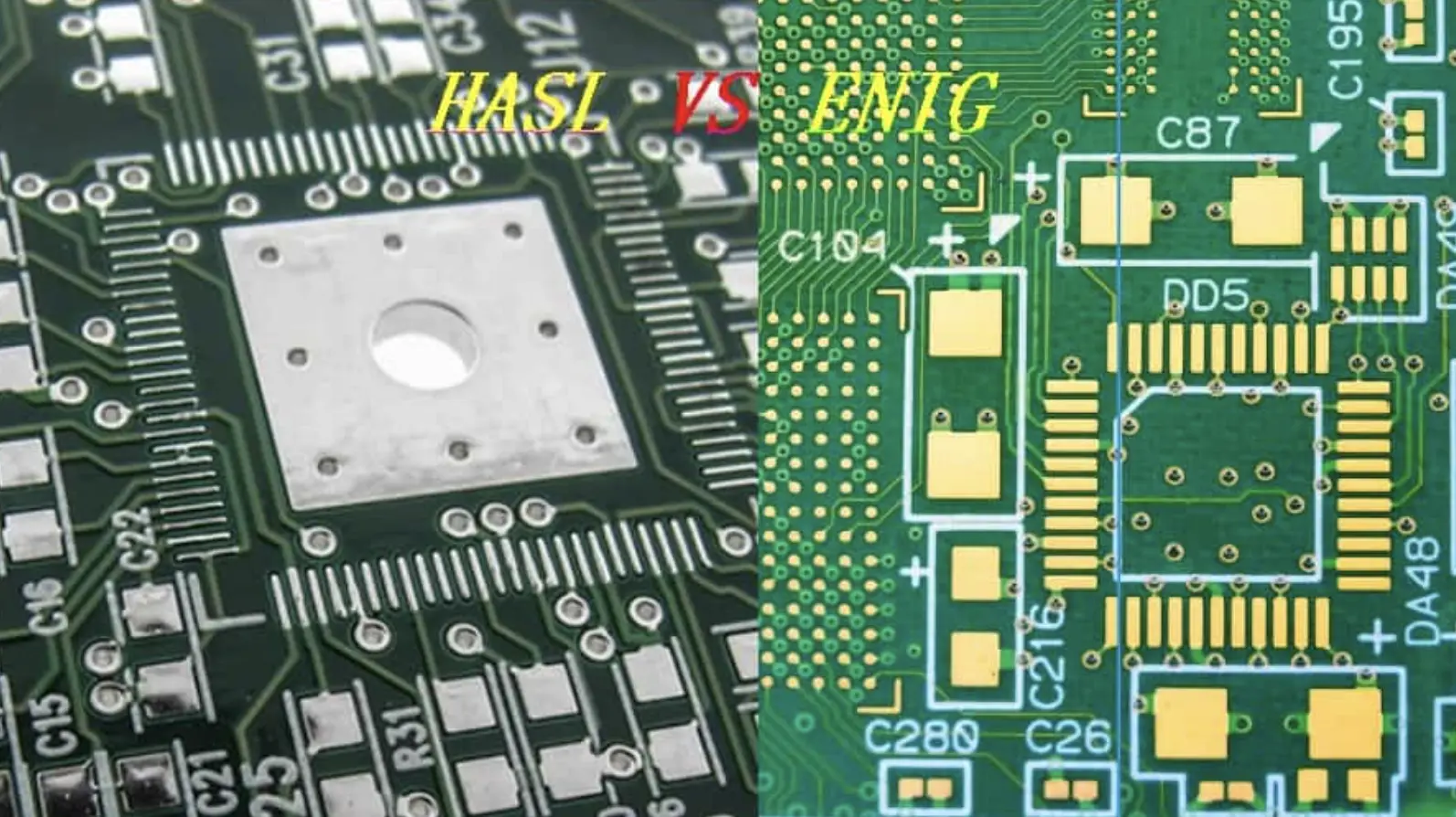
Several surface finishes suit SMT assembly, each with distinct characteristics suited to specific scenarios. Hot Air Solder Level (HASL) involves dipping boards in molten solder and leveling with hot air, creating a thick, tin-lead or lead-free coating. While cost-effective, its uneven topography makes it less ideal for fine-pitch components PCB, as it can cause solder beading during reflow. Lead-free HASL improves environmental compliance but retains similar coplanarity issues.
ENIG for SMT, or Electroless Nickel Immersion Gold, deposits a nickel barrier layer topped with thin gold, offering excellent flatness and oxidation resistance. This finish excels in fine-pitch applications due to uniform thickness, typically 0.05 to 0.1 microns of gold over 3-6 microns of nickel. It supports multiple reflow cycles and provides superior solder paste compatibility, making it a go-to for high-reliability boards. However, excessive phosphorus in the nickel can lead to brittle joints if not controlled.
Organic Solderability Preservative (OSP) applies a thin organic film that preserves copper's solderability until assembly. OSP reflow soldering works well in controlled environments, as the film burns off cleanly during heating, leaving fresh copper for wetting. Its low cost and environmental friendliness appeal to volume production, though it demands short shelf life and careful handling to avoid fingerprint contamination.
Immersion Tin and Immersion Silver offer alternatives with pure tin or silver coatings directly on copper. Immersion Tin provides good flatness and whisker resistance, while Immersion Silver delivers fast wetting but risks tarnishing in humid conditions. Each finish's performance hinges on matching it to the assembly process, such as vapor phase or convection reflow.
Technical Principles Governing Surface Finish Performance in SMT
Solderability, the ability of a finish to form a strong metallurgical bond with solder, depends on surface energy, oxide formation, and intermetallic growth. During reflow, the finish must allow flux in solder paste to clean the surface, enabling tin from the paste to wet and alloy with the underlying metal. For ENIG for SMT, the gold dissolves rapidly, exposing nickel for intermetallic formation with tin, but overexposure risks nickel corrosion known as black pad. OSP reflow soldering relies on the organic layer vaporizing without residue, preserving copper for direct tin-copper intermetallics.
Coplanarity is critical for fine-pitch components PCB, where pad-to-pad height variations exceed 25 microns can misalign stencil apertures. JEDEC J-STD-020E guidelines for moisture/reflow sensitivity highlight how finishes affect warpage during thermal excursions. Thicker finishes like HASL introduce more stress, potentially causing pad lifting, while thin-film options like ENIG minimize this.
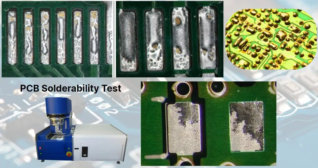
Solder paste compatibility involves flux chemistry matching the finish's activation needs. Water-soluble pastes pair well with OSP, as they remove residues effectively, whereas no-clean pastes suit ENIG to avoid gold embrittlement. Thermal profiles per IPC-6012E qualification specs test these interactions, ensuring joint integrity post-reflow. Engineers must validate finishes through wetting balance tests or dip-and-look simulations before full runs.
Process windows narrow with lead-free solders, demanding finishes resistant to higher reflow peaks around 260°C. Oxidation kinetics accelerate above this, so finishes with self-passivating layers, like Immersion Tin, maintain performance. Alloy diffusion rates also factor in, as excessive intermetallics weaken joints over time.
Best Practices for Selecting and Implementing SMT Assembly Finishes
Start by assessing board complexity: for fine-pitch components PCB under 0.4mm pitch, prioritize ENIG for SMT due to its planarity and reliability. Map assembly equipment capabilities, such as reflow oven profiles, to finish tolerances; OSP suits nitrogen-purged ovens for optimal OSP reflow soldering. Verify solder paste compatibility via DOE trials, printing paste on coupon panels and inspecting joints via X-ray or cross-section.
Compare finishes using a decision matrix focused on key metrics:
- HASL
- Coplanarity: Poor
- Shelf Life: Long
- Cost: Low
- Solderability: Good
- Fine-Pitch Suitability: Low
- ENIG
- Coplanarity: Excellent
- Shelf Life: Long
- Cost: Medium
- Solderability: Excellent
- Fine-Pitch Suitability: High
- OSP
- Coplanarity: Excellent
- Shelf Life: Short
- Cost: Low
- Solderability: Good
- Fine-Pitch Suitability: Medium
- Immersion Tin
- Coplanarity: Good
- Shelf Life: Medium
- Cost: Medium
- Solderability: Good
- Fine-Pitch Suitability: Medium
- Immersion Silver
- Coplanarity: Good
- Shelf Life: Medium
- Cost: High
- Solderability: Excellent
- Fine-Pitch Suitability: High
Incorporate handling protocols: store OSP boards in vacuum-sealed nitrogen packs and assemble within 24-48 hours. For high-volume SMT, qualify finishes per IPC standards to ensure Class 3 compliance. Preheat boards gradually to avoid thermal shock, and use edge supports in reflow to prevent sagging.
Post-assembly inspection follows IPC-A-600K criteria, checking for voids under 25% area or bridging over 0.1mm. Rework ENIG boards cautiously to prevent nickel exposure. Track yield data to refine selections iteratively.
Troubleshooting Common Surface Finish Issues in SMT Assembly
Poor solder wetting often stems from aged OSP, manifesting as dewet balls on pads. Diagnose by zeroing in on storage conditions; contaminated gloves or humidity spikes accelerate degradation. Switch to ENIG for SMT if repeated reflows are planned, and implement flux-upgrades for better activation.
Bridging in fine-pitch components PCB points to coplanarity flaws, common with HASL's nodular surface. Measure pad height variation with profilometers; if exceeding 75 microns, reprofile stencils or opt for flat finishes like Immersion Tin. Adjust paste volume to 75-125% aperture fill to compensate.
Tombstoning links to uneven heating across finish-coated pads. OSP reflow soldering exacerbates this if flux burns unevenly; test peak temperatures 5-10°C lower. Solder paste compatibility mismatches cause head-in-pillow defects, where paste balls resist merging; validate with thermal profilers matching JEDEC J-STD-020E curves.
Black pad on ENIG arises from etch-back during immersion gold, weakening nickel. Inspect via dye-and-peel; mitigate with controlled plating baths. For all issues, root-cause via 8D methodology, correlating finish specs to defect maps.
Conclusion
Choosing the optimal SMT assembly finish hinges on balancing solderability, coplanarity, and process compatibility for your specific application. ENIG shines for demanding fine-pitch components PCB, while OSP offers economical OSP reflow soldering in controlled setups. Prioritize solder paste compatibility and validate against standards like IPC-6012E to ensure robust joints. Practical troubleshooting and best practices will streamline production, reducing defects and costs. Equip your team with these insights to make informed decisions that enhance assembly success.
FAQs
Q1: What is the best SMT assembly finish for fine-pitch components PCB?
A1: ENIG for SMT provides superior coplanarity and solder wetting, ideal for pitches below 0.5mm. It withstands multiple reflows without degrading, minimizing bridging risks. Test solder paste compatibility to confirm joint strength, aligning with IPC guidelines for high-reliability boards. Avoid HASL due to its uneven surface.
Q2: How does OSP perform in reflow soldering processes?
A2: OSP reflow soldering excels in cost-sensitive runs with clean copper exposure post-vaporization. Limit shelf life to 24 hours and use nitrogen atmospheres to prevent oxidation. It offers good solder paste compatibility with no-clean fluxes, though handling demands care to avoid contamination. Yield drops if storage exceeds specs.
Q3: Why is solder paste compatibility crucial for PCB surface finishes?
A3: Incompatible paste flux fails to activate the finish properly, leading to voids or dewetting in SMT assembly. ENIG pairs well with low-residue pastes, while OSP needs aggressive activation. Profile reflows per JEDEC standards to match, ensuring intermetallic formation without excess residue.
Q4: Can ENIG be used for high-volume SMT assembly?
A4: Yes, ENIG for SMT supports high-volume lines with excellent flatness for fine-pitch components PCB. Its long shelf life reduces inventory turns, though plating costs are higher. Monitor for black pad via process controls, and it delivers reliable solder paste compatibility across profiles.
References
IPC-6012E — Qualification and Performance Specification for Rigid Printed Boards. IPC, 2017
IPC-A-600K — Acceptability of Printed Boards. IPC, 2020
JEDEC J-STD-020E — Moisture/Reflow Sensitivity Classification. JEDEC, 2014


