 ALLPCB


Why BGA Rework Safety Matters
BGA rework safety directly influences the reliability of electronic assemblies in demanding applications. Engineers must address potential hazards such as thermal stress, chemical exposure, and electrostatic discharge to prevent injuries and equipment failures. Without structured safety protocols, rework stations can experience accelerated wear on tools and fixtures. Safe BGA rework practices also reduce the likelihood of board warpage or delamination that leads to costly scrap. Incorporating BGA rework safety equipment into daily workflows supports compliance with established industry guidelines and improves overall process repeatability.
Common BGA Rework Hazards
Thermal hazards arise when hot air or infrared systems apply concentrated heat to localized areas of the board. Operators face risks of burns from contact with heated nozzles or from solder splatter during component lift-off. Chemical hazards develop from flux residues that release fumes when heated, potentially causing respiratory irritation over repeated exposure. Electrostatic discharge poses another concern, as charged tools or personnel can damage sensitive components during handling. Equipment hazards include overheating of rework stations that shortens the life of heating elements and causes inconsistent temperature profiles.
Related Reading: BGA Rework Demystified: A Practical Guide to Hot Air Techniques
Technical Principles Behind Safe BGA Rework
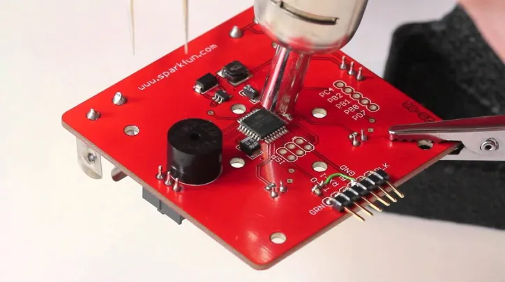
Heat transfer during BGA rework follows principles of conduction and convection that must be managed to limit thermal gradients across the board. Excessive temperature differences can induce warpage, particularly on thin or multilayer substrates. Flux activation and solder reflow occur within narrow time and temperature windows defined by component specifications. Ventilation systems remove airborne particles and vapors generated during these thermal cycles, maintaining acceptable air quality in the work area. Electrostatic control relies on grounding paths and dissipative materials that equalize potential differences before contact occurs.
Related Reading: BGA Rework for Beginners: A Hobbyist's Guide to Repairing Electronics
Practical Solutions and Best Practices
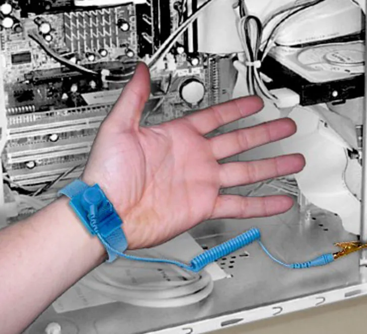
Engineers implement BGA rework safety equipment such as localized exhaust hoods and filtered air systems to capture fumes at the source. Temperature profiling tools allow operators to verify that peak temperatures stay within safe limits for both the component and the board substrate. Personal protective equipment includes heat-resistant gloves, safety glasses, and respirators rated for organic vapors when ventilation alone proves insufficient. Grounding wrist straps and conductive work surfaces form the foundation of electrostatic discharge prevention during every handling step. Regular calibration of rework equipment ensures that actual temperatures match programmed profiles and reduces the chance of overheating events.
Safe BGA rework practices begin with a pre-rework inspection that identifies moisture-sensitive devices requiring baking. Operators follow a structured sequence that includes flux application, controlled ramp rates, and component removal with minimal mechanical force. Post-rework cleaning removes flux residues that could affect long-term reliability. Documentation of each profile and safety check supports traceability and helps identify recurring issues in the process.
Equipment Protection Measures
Protecting rework equipment starts with maintaining proper airflow around heating elements to prevent premature failure. Scheduled inspections of nozzles and sensors detect wear before it affects process control. Using compatible fixtures that distribute mechanical load evenly reduces stress on the station frame during component placement. Software limits on maximum temperature and dwell time provide an additional layer of protection against operator error. These steps extend the service life of capital equipment while preserving the accuracy required for fine-pitch BGA work.
Conclusion
BGA rework safety combines engineering controls, personal protective measures, and disciplined process execution to safeguard personnel and equipment. Consistent application of these principles supports higher first-pass yields and reduces unplanned downtime. Engineers who prioritize ventilation, thermal management, and electrostatic precautions create safer and more reliable rework environments.
FAQs
Q1: What are the primary BGA rework hazards that engineers should address first?
A1: The main concerns include thermal burns, flux fume exposure, and electrostatic discharge that can damage components or cause operator discomfort. Addressing these through proper ventilation and grounding reduces risk during repeated rework cycles. Engineers also monitor equipment for overheating that could shorten tool life.
Q2: How does BGA rework ventilation contribute to safe BGA rework practices?
A2: Effective ventilation captures and removes vapors generated during flux activation and solder reflow, maintaining air quality at the workstation. This approach complements personal protective equipment and helps operators remain focused throughout the process. Regular filter maintenance ensures continued performance.
Q3: Which BGA rework safety equipment provides the best protection against electrostatic discharge?
A3: Grounding wrist straps, conductive mats, and ionized air blowers form a complete system that equalizes potential before components are handled. These items integrate easily into existing rework stations without interfering with thermal operations. Routine verification of grounding resistance confirms ongoing effectiveness.
Q4: What steps help protect rework equipment during BGA component replacement?
A4: Calibrating temperature controllers and using appropriate fixtures prevent excessive stress on heating elements and mechanical arms. Scheduled cleaning of sensors and nozzles maintains profile accuracy over time. Following manufacturer-recommended maintenance intervals supports consistent performance across multiple jobs.
References
IPC-7711/7721B — Rework, Modification and Repair of Electronic Assemblies. IPC, 2017
JEDEC J-STD-020E — Moisture/Reflow Sensitivity Classification for Nonhermetic Surface Mount Devices. JEDEC, 2014
IPC-A-610G — Acceptability of Electronic Assemblies. IPC, 2017


