ALLPCB


Introduction
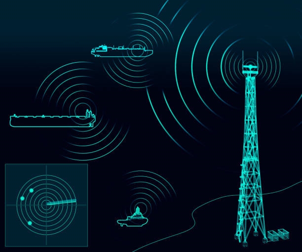
This article explains why S-parameters are the de facto standard in the RF domain.
Other network parameters and practical limitations
Besides S-parameters, there are other network parameter sets such as Y-parameters, Z-parameters, H-parameters, and ABCD-parameters. Their definitions often require setting voltages or currents to zero, which corresponds to open-circuit or short-circuit conditions. At microwave and millimeter-wave frequencies, producing precise open- or short-circuit terminations across a wide bandwidth is difficult. When the required boundary conditions are hard to realize, extracting those parameters reliably becomes challenging.
S-parameters and wave variables
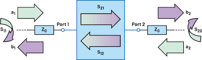
S-parameters are defined in terms of incident and reflected traveling waves rather than total voltages or currents at ports. For a port n, the total voltage Vn is decomposed into Vn+ (incident wave) and Vn- (reflected wave); the sum Vn+ + Vn- gives the total voltage at the reference plane. Setting the incident wave on a given port to zero (for example ak = 0) means there is no incoming wave on that port, but it does not require the total voltage to be zero. This distinction is important.
When evaluating a specific S-parameter such as S21, one sets the incident waves on all ports except port 1 to zero (a2 = a3 = ... = an = 0) and applies a1. The reflected waves an at other ports originate at the load terminations. If the load is matched, those reflected waves an will be zero. Achieving matched loads is comparatively straightforward, even over wide bandwidths and at high frequencies, which makes S-parameter measurements practical and robust.
How to separate incident and reflected waves in practice
In practice, decomposing the total port voltage into Vn+ and Vn- is done with directional couplers, which are core components of vector network analyzers (VNAs). An ideal directional coupler has four ports commonly labeled input (incident), through, coupled, and isolated.
If a signal enters port 1, the coupled port (port 3) sees the coupled portion while the isolated port (port 4) ideally sees nothing. Conversely, if a reflected wave returns into port 2, that reflected signal appears at port 4 and not at port 3 (for an ideal coupler). Directional couplers thus enable measurement of incident and reflected wave amplitudes needed to compute S-parameters.
Conclusion
The practical advantages of S-parameter definitions, which rely on incident and reflected waves and require only matched terminations rather than absolute open- or short-circuits, explain their widespread adoption in RF and microwave engineering. Directional couplers and VNAs provide the measurement infrastructure that makes S-parameter characterization feasible over wide frequency ranges.