 ALLPCB


Introduction
A heavy snowfall in Beijing prompted the author to revisit a piano arrangement of "Snowdream" and an earlier clarinet rendition. Today we continue examining the "D" in DMG, where D stands for Directional in IEEE 802.11ad. This directionality is achieved through a carefully designed beam training protocol.
Overview
Propagation at 60 GHz differs significantly from traditional 2.4/5 GHz Wi?Fi. Consequently, IEEE 802.11ad incorporates specific measures for this band. The "D" in DMG indicates directional transmission, a key design element in 11ad. Unlike omnidirectional propagation used in conventional Wi?Fi, 11ad relies on high?gain, narrow beams to focus energy and compensate for increased path loss.
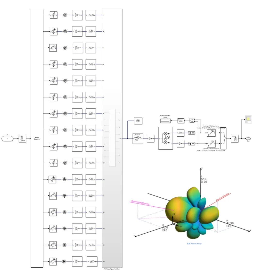
Directionality and high gain are commonly realized with phased antenna arrays, either by precomputing antenna weighting vectors or by using multiple directional arrays. Example:
At 60 GHz the wavelength is about 5 mm and typical element spacing is around 2.5 mm, allowing much smaller antenna form factors than 2.4/5 GHz Wi?Fi. The photo below shows an RF plus antenna module for 11ad with dimensions of roughly 17 mm × 8 mm.
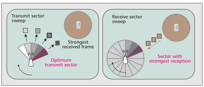
DMG uses antenna sector scanning. The illustration below shows two nodes communicating via virtual sectors: with no obstructions, choosing sectors aligned with the line of sight yields the best link quality. Since each sector concentrates antenna gain in a given direction, matching the best transmit and receive sectors is necessary to optimize signal quality and throughput. This process is beamforming training. Note that this is different from 5G Massive MIMO, since only one antenna array is used at a time.
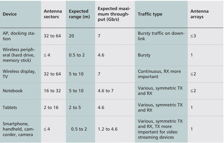
Device classes differ in the number of antenna arrays they have. Handheld devices may use low?complexity arrays (1–4 arrays), while mains?powered devices can host multiple arrays. The table below shows typical configurations for several device types, including numbers of sectors related to range and throughput, transmit/receive asymmetries, traffic characteristics, and expected array counts. Multiple phased arrays can provide high?gain coverage in all directions.
Higher antenna gain is generally desirable but increases directionality and the number of narrow sectors, which raises the overhead to align antenna pointing between nodes. Misalignment losses also grow with increased directionality, so there are trade?offs. Highly directional transmission reduces out?of?beam interference and enables spatial reuse of the same band, improving system throughput. However, it complicates common Wi?Fi MAC mechanisms. Directional modes prevent passive listening to ongoing transmissions, increasing collision risk during channel access. Mismatched transmit or receive modes can cause frame loss and throughput degradation.
When the relative direction between paired devices is unknown, as during beamforming training, a DMG STA uses a quasi?omni antenna pattern. It is called "quasi" because realizing a true omnidirectional pattern at millimeter wave frequencies is impractical: nearby components block and perturb signals much more than at traditional Wi?Fi frequencies. Propagation loss at millimeter waves further reduces range and throughput in quasi?omni mode, so at least one end of the link typically needs directional gain to achieve sufficient range. Quasi?omni is usually used at the receiver. The DMG specification requires that the main beam antenna gain of a quasi?omni pattern be no more than 15 dB lower than that of a directional main beam.
Beamforming: Two Stages
Beamforming (BF) in 11ad is a mechanism that a pair of STAs use to establish the DMG link required for subsequent communication. Beamforming training is a bidirectional sequence of beamforming frame exchanges that employs sector scanning and the necessary signaling to let each STA determine appropriate antenna system settings for transmit and receive. When BF training completes successfully, the beamformed link is established. BF frames include SSW frames, DMG beacon frames, SSW?feedback frames, SSW?acknowledge frames, or BRP frames. The example below illustrates the beamforming training process.
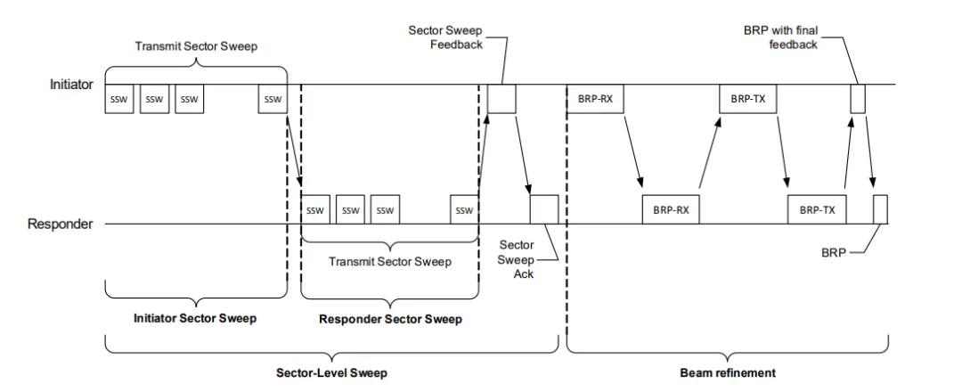
BF consists of two stages: SLS and BRP.
- SLS: Sector Level Sweep, the sector scanning stage.
- BRP: Beam Refinement Protocol, the beam refinement stage.
During SLS, initial coarse?grained antenna sector configurations are determined. This information can then be used in the optional BRP stage to fine tune the selected sectors. Fine tuning involves evaluating antenna weight vectors other than the predefined sector patterns to optimize phased array transmission. In SLS, each STA trains its transmit or receive antenna sectors. When a device has sufficient transmit antenna gain, it is common to train only transmit sectors during SLS and derive the receive configuration during a subsequent BRP. With both ends fully refined for transmit and receive sectors, multi?Gbps rates are achievable at ranges on the order of 10 meters.
There are several options for implementing beamforming. Generally, during SLS a pair of STAs exchanges a series of Sector Sweep (SSW) frames across different antenna sectors to find the sectors that provide the highest signal quality. Each STA acts as transmitter and receiver in separate sweeps. The STA that transmits during a sweep is the initiator; the other STA is the responder. During a transmit sector sweep, frames are sent from different sectors while the paired node receives in a quasi?omni mode. To identify the best transmit sector, the initiator tags each frame with the antenna and sector identifier used. During a receive sector sweep, transmissions on the same sector test the paired node's best receive sector. The achieved best SNR and, for transmit sweeps, the sector and antenna identifiers, are reported back to the paired node.
If both STAs have sufficient transmit antenna gain, their SLS phase can consist entirely of transmit sector training, with receive sector training deferred to BRP. Devices with fewer antenna arrays must increase receive gain to obtain enough link budget for link establishment and therefore are likely to include receive sector sweeps in their SLS exchanges.
The BRP refines sectors discovered during SLS. These sectors might exhibit suboptimal signal quality, and for phased arrays BRP can optimize antenna weight vectors. BRP provides multiple optional refinement mechanisms in an iterative process, where initiator and responder can request training of receive or transmit antenna patterns. BRP can test different antenna configurations within a single frame, greatly reducing overhead compared with SLS, which needs an entire frame per tested sector. To scan antenna configurations within a frame, BRP frames include transmit and receive training fields (TRN?T / TRN?R). Each field is used to send or receive with the antenna configuration to be tested. The rest of the frame is sent and received using the currently known best antenna configuration. Like SLS, BRP feedback reports the best discovered configuration as SNR and the best configuration ID.


