 ALLPCB


Introduction
Automotive electronics face relentless challenges from transient voltage spikes that can damage sensitive components and disrupt vehicle systems. TVS diodes, or transient voltage suppression diodes, serve as critical safeguards by rapidly clamping excessive voltages to safe levels. These devices are essential in modern vehicles with increasing electrification, including electric vehicles and advanced driver-assistance systems. Engineers must prioritize automotive transient voltage protection to ensure reliability under harsh operating conditions. This article explores TVS diode selection, key parameters like clamping voltage and response time, and alignment with relevant standards.
Understanding TVS Diodes and Their Role in Automotive Systems
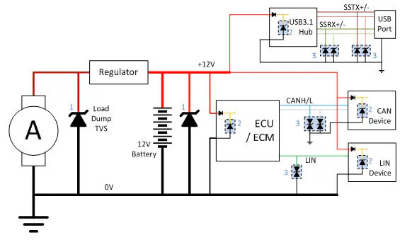
TVS diodes operate on the principle of avalanche breakdown, activating when voltage exceeds the breakdown threshold to shunt surge current away from protected circuits. In automotive applications, they protect power supplies, sensors, and communication lines from spikes generated by events like load dumps or inductive switching. Unlike standard zener diodes, TVS diodes are optimized for high-speed response and energy absorption, making them ideal for transient events lasting microseconds. Their bidirectional or unidirectional configurations allow flexibility in circuit placement. Proper TVS diode selection ensures minimal impact on normal operation while providing robust defense.
These diodes maintain low leakage current under normal voltages, preserving system efficiency. Automotive electronics demand devices that withstand repeated surges without degradation.
Sources of Transient Voltage Spikes in Automotive Environments
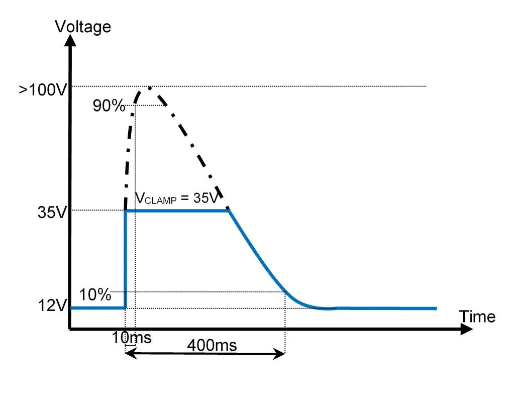
Automotive transients arise from multiple sources, including battery disconnections during alternator operation, known as load dumps, which produce high-voltage pulses. Switching of inductive loads like relays and motors generates negative and positive spikes. Electrostatic discharge from human contact or environmental factors adds fast, high-energy events. Supply line interruptions and conducted disturbances further threaten electronic control units and infotainment systems. Understanding these sources guides effective automotive transient voltage protection strategies.
Load dumps, in particular, can exceed nominal battery voltages significantly, stressing unprotected circuits. Engineers simulate these using standardized waveforms to validate protection.
Key Parameters for TVS Diode Selection
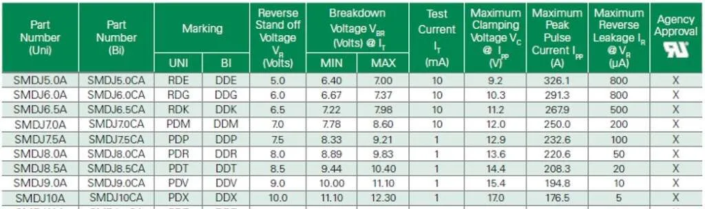
TVS diode selection hinges on several critical parameters tailored to automotive demands. The reverse standoff voltage must exceed the circuit's normal operating voltage to avoid conduction during steady-state conditions. Breakdown voltage sets the activation point, slightly above standoff for reliable triggering. Clamping voltage determines the protected voltage level during a surge, ensuring it stays below the maximum rating of downstream components. Engineers evaluate these alongside expected surge profiles for optimal fit.
TVS diode response time, often in the picosecond range, enables near-instantaneous clamping, outpacing many other protection methods. This speed is vital for high-frequency transients like ESD.
Peak pulse power rating indicates the diode's capacity to dissipate surge energy without failure, specified for standard waveforms like 8/20 microseconds. Surge current handling, or peak pulse current, measures the maximum current the device endures at a given clamping voltage. Higher ratings suit severe automotive environments, but oversizing increases cost and size unnecessarily. Balancing these ensures comprehensive protection.
TVS diode peak pulse power and surge current ratings must align with application threats, such as those from ISO 7637-2 pulses.
| Parameter | Description | Automotive Consideration |
|---|---|---|
| Clamping Voltage (Vc) | Voltage across diode during surge at specified Ipp | Must be < max IC voltage |
| Response Time | Time to clamp transient | <1 ps for ESD protection |
| Peak Pulse Power (Ppp) | Max power dissipation capability | Matches expected surge energy |
| Surge Current (Ipp) | Max current at Vc for 8/20 μs wave | Handles load dump currents |
| Reverse Standoff Voltage (VRWM) | Max DC voltage without conduction | > Nominal bus voltage (e.g., 12V/24V systems) |
Automotive Standards for Transient Protection
Industry standards define transient severity, guiding TVS diode automotive standards compliance. ISO 7637-2 specifies electrical transients on supply lines, including load dump pulses that test protection efficacy. These pulses simulate real-world disconnections, requiring devices to clamp without failure. IEC 61000-4-2 outlines ESD levels, demanding fast response times from TVS diodes. Adhering to these ensures system robustness across global markets.
ISO 16750-2 complements by addressing environmental conditions and electrical loads, emphasizing surge withstand. TVS diodes qualified under these frameworks provide verified performance.
Best Practices for TVS Diode Implementation
Place TVS diodes as close as possible to protected components to minimize parasitic inductance effects. Use low-ESR capacitors in parallel for low-frequency energy absorption, complementing the diode's high-speed action. Select bidirectional TVS for AC-coupled lines or unknown polarity surges. During TVS diode selection, derate peak pulse power by 50% for safety margins in prolonged exposure scenarios. Thermal management via adequate PCB copper area prevents overheating during repetitive surges.
Test circuits against standard pulses to validate clamping voltage and surge current handling. Multi-stage protection, with a high-power TVS at the input and lower-power at IC pins, optimizes performance. Monitor junction temperature rise under load.
Troubleshooting Common Issues in Automotive TVS Deployments
Engineers often encounter TVS diodes failing prematurely due to undersized peak pulse power for actual surges. Symptoms include charred devices or recurring IC latch-ups post-transient. Verify TVS diode clamping voltage suits the application by scoping real transients. Response time mismatches cause overshoot; replace with faster devices if needed. Surge current exceeding ratings leads to avalanche wear-out over time.
Poor grounding amplifies issues, as return paths for surge current become inductive. Recheck PCB layout for short, wide traces. Simulate with tools modeling ISO waveforms before prototyping.
In one scenario, a control module suffered intermittent resets from unmitigated load dumps. Adding a TVS with adequate TVS diode surge current rating resolved it, confirming protection via post-test analysis.
Conclusion
TVS diodes form the cornerstone of automotive transient voltage protection, addressing spikes from diverse sources effectively. Key to success lies in precise TVS diode selection based on clamping voltage, response time, peak pulse power, and surge current. Alignment with standards like ISO 7637-2 ensures reliability in demanding environments. Implementing best practices minimizes risks, enhancing vehicle electronics longevity. Engineers benefit from methodical parameter evaluation and validation testing for optimal outcomes.
FAQs
Q1: How does TVS diode clamping voltage influence automotive transient voltage protection?
A1: Clamping voltage defines the maximum voltage seen by protected circuits during a surge. It must remain below the IC's absolute maximum rating to prevent damage. In automotive systems, select based on expected transients like load dumps. Lower clamping aids tighter protection but may increase leakage. Verify through waveform analysis.
Q2: What role does TVS diode response time play in ESD events?
A2: TVS diode response time, typically under 1 picosecond, ensures clamping before ESD energy damages components. This speed surpasses slower fuses or varistors. Automotive applications demand this for IEC 61000-4-2 compliance. Faster response reduces let-through voltage effectively.
Q3: How to evaluate TVS diode peak pulse power for surge current in vehicles?
A3: Match peak pulse power to the energy of anticipated surges, such as ISO 7637-2 pulses. Surge current rating at clamping voltage guides sizing. Derate for repetition and temperature. Higher ratings handle severe automotive conditions reliably.
Q4: What are TVS diode automotive standards for qualification?
A4: Standards like ISO 7637-2 and ISO 16750-2 define transient tests for validation. TVS diodes must withstand specified pulses without degradation. IEC standards cover ESD and surges. Compliance verifies suitability for harsh environments.
References
ISO 7637-2 — Road vehicles — Electrical disturbances from conduction and coupling. ISO
ISO 16750-2 — Road vehicles — Environmental conditions and testing for electrical and electronic equipment. ISO
IEC 61000-4-2 — Electromagnetic compatibility — Part 4-2: Testing and measurement techniques — Electrostatic discharge immunity test. IEC
IEC 61000-4-5 — Electromagnetic compatibility — Part 4-5: Testing and measurement techniques — Surge immunity test. IEC


