 ALLPCB


Introduction
Selective soldering serves as a precise method for attaching through-hole components to printed circuit boards after surface-mount technology assembly. This process uses a targeted solder fountain or mini-wave to apply molten solder only to specific areas, minimizing thermal stress on nearby sensitive parts. Engineers often encounter selective soldering defects that compromise joint reliability and assembly yield. Addressing these issues requires understanding root causes rooted in process parameters, material interactions, and design factors. Effective troubleshooting enhances product quality and reduces rework costs in high-mix production environments. This article explores key selective soldering defects, their mechanisms, and proven solutions tailored for electrical engineers.
What Is Selective Soldering and Why It Matters
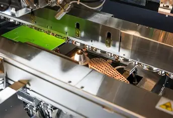
Selective soldering involves a robotic system that drops a solder pot nozzle precisely onto component leads protruding through plated-through holes. Unlike wave soldering, it avoids flooding the entire board, making it ideal for mixed-technology assemblies with both SMT and through-hole parts. The process relies on flux activation, preheating, soldering, and drag-off stages to achieve proper wetting and fillet formation. Defects in selective soldering can lead to electrical shorts, open circuits, or mechanical failures, impacting long-term reliability in applications like power supplies and industrial controls. Troubleshooting these selective soldering defects ensures compliance with industry benchmarks and optimizes throughput. For electric engineers, mastering this directly supports robust design validation and process control.
Understanding the Causes of Selective Soldering Defects
Selective soldering defects arise from imbalances in thermal profiles, flux performance, nozzle dynamics, and board preparation. Insufficient preheating fails to drive out moisture or activate flux adequately, hindering solder flow into holes via capillary action. Excessive solder volume or improper drag speeds promote bridging between closely spaced pins. Material incompatibilities, such as pad finish degradation, contribute to poor adhesion and lifting. Process monitoring tools like thermal profilers reveal these anomalies early. Aligning parameters with standards like IPC J-STD-001 prevents recurrence across production runs.
Solder Bridging: Identification and Prevention
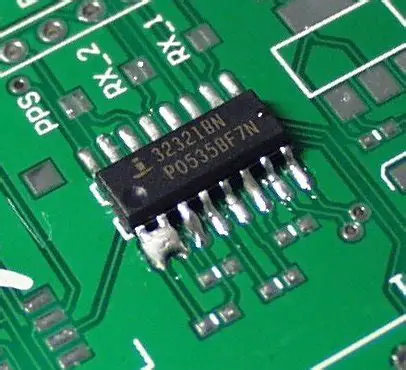
Solder bridging occurs when excess molten solder connects adjacent leads, creating unintended electrical paths. This selective soldering defect manifests as shiny bridges visible under magnification, often between fine-pitch connectors. Primary causes include nozzles too wide for lead spacing, high solder pot temperatures causing over-flow, or slow drag-off rates that allow solder to slump. Flux residue buildup on the nozzle can also exacerbate bridging by altering surface tension. According to IPC-A-610 acceptability criteria, any bridge wider than a lead thickness constitutes a defect requiring rework. Visual inspection post-soldering quickly flags these issues before functional testing.
To mitigate solder bridging, select drop-jet nozzles matched to the minimum lead pitch, typically ensuring a 0.5 mm clearance margin. Optimize drag-off angles at 5 to 10 degrees with speeds around 10 to 20 mm per second to shear excess solder cleanly. Reduce flux drop volume to just coat leads without overflow, and maintain consistent preheats between 120 and 150 degrees Celsius for uniform wetting. Regular nozzle cleaning prevents residue accumulation that promotes bridging. Implementing these adjustments in process recipes yields defect rates below 1% in qualified lines. Engineers should profile each new board family to fine-tune parameters.
Solder Balling: Mechanisms and Control Strategies
Solder balling involves discrete spheres of solder detaching and scattering across the board surface during selective soldering. These balls pose risks of shorts if dislodged during handling or vibration. Flux splatter from high-drop heights, contaminated solder pots, or rapid cooling rates trigger this defect by disrupting flux-solder interactions. Outgassing from inadequate preheat volatilizes flux prematurely, ejecting balls onto nearby SMT pads. Ball sizes range from pinpoint to pinhead, detectable via automated optical inspection. Controlling solder balling maintains clean assemblies compliant with cleanliness standards.
Effective solutions start with low-velocity flux applicators positioned close to the board, around 10 to 20 mm, to minimize airborne droplets. Use alcohol-based, low-residue fluxes with optimal activation temperatures matching the solder alloy. Preheat boards to stabilize flux and promote smooth reflow, avoiding thermal shocks. Post-solder nitrogen purging sweeps away potential balls during cooling. Filter solder pots regularly to remove oxides and dross that seed ball formation. These practices, combined with SPI verification, eliminate solder balling in most scenarios.
Insufficient Hole Fill: Achieving Reliable Barrel Wetting
Insufficient hole fill leaves plated-through holes partially voided, weakening mechanical strength and thermal conductivity. This common selective soldering defect shows as incomplete solder rise on the top side or visible barrel gaps in cross-section. Causes trace to small pin-to-hole ratios below 0.6:1, low solder immersion depths, or inadequate flux penetration. Cold boards resist capillary rise, trapping air pockets that starve the barrel. IPC J-STD-001 outlines minimum fill requirements for high-reliability joints. Cross-sectional analysis confirms fill percentages during process development.
Solutions emphasize design-for-manufacturability with pin diameters at least 60% of hole size for optimal wicking. Increase immersion time to 3 to 5 seconds per side, ensuring full nozzle contact without bridging risk. Boost flux quantity proportionally to hole count and preheat to 130 degrees Celsius minimum for flux efficacy. Dual-drop fluxers enhance bottom-side coverage for deeper barrels. Verify with X-ray or slice-and-etch methods initially, then transition to production AOI. Consistent application yields 100% fill reliably.
Fillet Lifting: Addressing Adhesion Failures
Fillet lifting appears as the solder heel or toe detaching from the pad, often with underlying land erosion. This defect signals excessive heat dissolving copper or poor intermetallic formation. Selective soldering's prolonged exposure to hot nozzles accelerates pad dissolution compared to reflow. Brittle flux residues or contaminated surfaces exacerbate lifting by weakening bonds. Exposed base material under the fillet indicates acceptability failure per IPC-A-610. Early detection via dye-and-peel testing prevents field failures.
Prevent fillet lifting by limiting dwell times to under 4 seconds and using immersion tin or ENIG pad finishes resistant to erosion. Select fluxes with balanced activity to avoid aggressive copper attack. Maintain solder temperatures 20 to 30 degrees Celsius above liquidus without excess. Post-process inspections focus on fillet concavity and adhesion. If lifting occurs, analyze via thermal profiling to correlate with nozzle height. Refined recipes restore fillet integrity across assemblies.
Selective Soldering Rework: Efficient Defect Correction
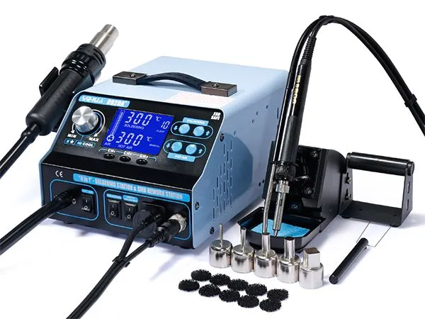
Selective soldering rework targets isolated defects without full disassembly. For bridging or balling, use hot air pencils at 300 degrees Celsius with flux to reflow and wick away excess. Insufficient fill demands precise solder fountain re-immersion or hand-soldering with controlled tips. Fillet lifting may require pad repair per IPC-7711/7721 guidelines before re-soldering. Automated rework stations with vision alignment speed high-volume fixes. Document each intervention to refine upstream processes. This approach minimizes scrap while upholding joint quality.
Best Practices for Defect-Free Selective Soldering
Implement a DOE matrix varying flux volume, preheat, speed, and nozzle type to baseline each product. Standardize pallet fixturing to combat warpage, ensuring flatness under 0.75% per IPC-6012. Train operators on real-time monitoring with thermocouples and flux meters. Integrate inline AOI and SPI for 100% inspection of critical nets. Audit processes weekly against defect Pareto charts. Collaborative design reviews incorporate DFM rules like lead protrusion and spacing early.
Conclusion
Troubleshooting selective soldering defects demands a systematic approach blending process control, material selection, and standards adherence. Addressing solder bridging, solder balling, insufficient hole fill, and fillet lifting through targeted solutions boosts yield and reliability. Selective soldering rework serves as a vital safety net for inevitable outliers. Electric engineers benefit from proactive DFM and monitoring to preempt issues. Adopting these strategies aligns assemblies with IPC benchmarks, ensuring robust performance in demanding applications.
FAQs
Q1: What causes solder bridging as a selective soldering defect?
A1: Solder bridging in selective soldering stems from oversized nozzles relative to pin pitch, excessive flux or solder volume, and suboptimal drag-off speeds. High temperatures promote solder slumping between leads. Proper nozzle sizing with at least 0.5 mm margins and controlled immersion depths prevent this. Preheating stabilizes surfaces for clean withdrawal. These adjustments comply with IPC-A-610 criteria for joint separation.
Q2: How can engineers fix insufficient hole fill in selective soldering?
A2: Insufficient hole fill results from poor pin-to-hole ratios, low preheats, or shallow immersion. Optimize ratios above 0.6:1, preheat to 130 degrees Celsius, and extend dwell times to 4 seconds. Enhanced flux application ensures capillary action. Verify via X-ray for full barrel wetting per J-STD-001. Iterative profiling resolves persistent voids effectively.
Q3: What are solutions for solder balling during selective soldering?
A3: Solder balling arises from flux splatter, contamination, or rapid cooling. Use precise droppers at low heights, clean solder pots, and nitrogen atmospheres. Select low-residue fluxes matching alloy melt points. Post-cool purging removes strays. AOI confirms ball-free boards. These steps minimize rework needs.
Q4: When does fillet lifting occur in selective soldering rework?
A4: Fillet lifting happens from pad dissolution, excessive heat, or flux incompatibility. Limit dwells under 4 seconds and use erosion-resistant finishes. Rework with IPC-7711 techniques repairs pads before re-soldering. Thermal analysis pinpoints causes. Proper flux selection prevents recurrence.


