 ALLPCB


Introduction
X-ray inspection plays a critical role in PCB quality control by revealing hidden defects in solder joints, vias, and multilayer structures that optical methods cannot detect. Technicians rely on these systems to ensure compliance with high-reliability standards in electric engineering applications. However, common x-ray problems such as image artifacts and hardware malfunctions can compromise accuracy, leading to false defect calls or missed issues. This guide addresses x-ray inspection troubleshooting, focusing on prevalent challenges in factory environments. By understanding these issues, technicians can maintain system performance and uphold production efficiency. Effective x-ray maintenance directly supports consistent PCB quality assurance.
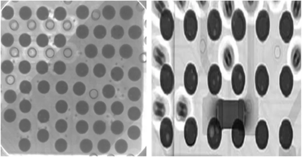
Understanding X-Ray Inspection in PCB Manufacturing
X-ray inspection uses penetrating radiation to produce images of PCB internal features, distinguishing dense materials like solder from lighter substrates. In automated X-ray inspection (AXI) systems, a tube generates X-rays that pass through the board onto a digital detector, forming grayscale images where defects appear as anomalies in contrast or shape. This method excels at inspecting bottom-terminated components such as BGAs and QFNs, where solder joints are obscured. Factory-driven processes integrate AXI post-reflow to verify joint integrity without destructive testing. Its relevance grows with denser PCB designs in electric engineering, demanding precise defect detection. Regular use ensures adherence to industry benchmarks for reliability.
Why Troubleshooting X-Ray Inspection Matters
Undetected common x-ray problems can cascade into production delays, increased scrap rates, and unreliable assemblies that fail in the field. For electric engineers, pristine X-ray images are essential for validating complex interconnections in high-stakes applications like power electronics. Poor image quality obscures critical flaws, risking non-compliance with standards like IPC-A-610, which defines acceptability criteria for solder joints. Proactive x-ray repair and maintenance minimize downtime in high-volume lines. Ultimately, robust troubleshooting sustains quality control, protecting end-product performance. Technicians who master these skills contribute to factory-wide efficiency.
Common X-Ray Image Issues and Their Causes
Blurry images represent one of the most frequent x-ray image issues, often stemming from mechanical vibration or improper exposure parameters. During scanning, even slight board movement relative to the source and detector axis causes motion blur, mimicking actual defects like poor wetting. Incorrect kilovoltage (kV) or milliampere (mA) settings fail to penetrate dense areas adequately, resulting in out-of-focus representations of vias or barrels. Tube focal spot degradation over time exacerbates this, as worn anodes produce larger effective spots that reduce sharpness. Factory technicians note that environmental factors, such as loose fixtures, compound these problems in continuous operation. Addressing blur promptly prevents misinterpretation during routine inspections.
High noise levels in X-ray images degrade contrast, making subtle voids or cracks indistinguishable from background graininess. This arises from insufficient X-ray flux, where short exposure times or low tube current limit photon count on the detector. Aging detectors accumulate dead pixels, introducing fixed pattern noise that persists across scans. Scatter radiation from high-density components like copper planes further dilutes signal-to-noise ratio, particularly in thick multilayer boards. In PCB lines, inconsistent power supply to the generator can fluctuate output, amplifying noise during peak loads. Recognizing these patterns allows quick parameter adjustments to restore clarity.
Distortion and geometric artifacts plague tilted or misaligned setups, warping joint shapes in the image plane. Source-to-detector distance mismatches cause magnification errors, where peripheral BGAs appear stretched compared to center ones. Detector tilt introduces pincushion or barrel distortion, complicating void percentage measurements per IPC-7095 guidelines. Multi-layer scatter creates halo effects around vias, simulating delamination. Vibration-isolated tables mitigate this, but worn stages lead to repeatable offsets. Technicians must verify alignment routinely to ensure accurate spatial representation.
Streaks or ghosting indicate tube arcing or contamination, where electrical discharge paths leave linear burns on images. Overheating from inadequate cooling cycles precipitates filament failures, producing inconsistent beams. Filter blockages trap debris, altering spectrum and causing uneven illumination. These x-ray maintenance oversights manifest as intermittent faults, halting automated runs. Early detection via log reviews prevents escalation to full system downtime.
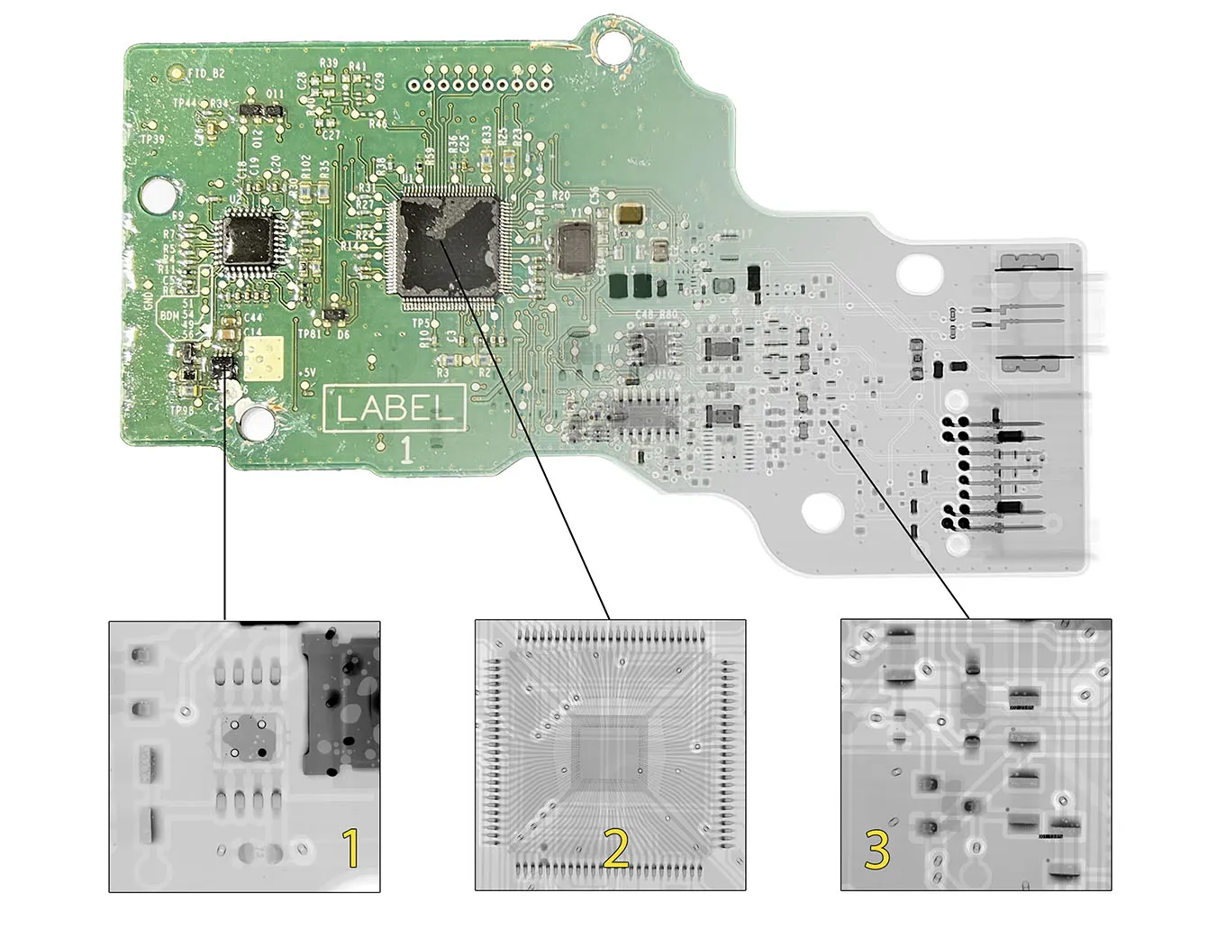
Hardware-Related Common X-Ray Problems
X-ray tube failures top hardware concerns, with lifespan typically measured in hours before output drops. Symptoms include dim images or error codes signaling high voltage instability, often from cooling pump malfunctions. In factory settings, dust ingress accelerates anode wear, demanding cleanroom protocols. Replacement involves precise realignment to avoid geometry shifts. Technicians track usage logs to schedule preemptively, aligning with preventive x-ray maintenance schedules.
Detector degradation presents as pixel dropouts or blooming, where saturated areas bleed into neighbors. Flat-panel detectors suffer radiation damage over time, reducing dynamic range. Cleaning residue from the scintillator layer restores sensitivity, but deeper issues require vendor calibration. Vibration shocks loosen connections, mimicking failures. Regular gain-offset corrections compensate for drift.
Motion system glitches, like stage binding, cause positioning errors that repeat across boards. Worn belts or encoders lead to drift, misregistering ROIs in software. Lubrication and backlash checks form core x-ray repair routines. Overloads from heavy panels strain motors, triggering safeties.
Power supply fluctuations underlie many intermittent faults, with ripple affecting kV stability. Capacitor aging in high-voltage units causes voltage sags, dimming outputs. Fuse blows from surges protect but interrupt flows. Backup generators ensure continuity in plants.
Software and Calibration Challenges
Software glitches freeze interfaces or corrupt image stacks, often from memory overflows in high-res modes. Outdated firmware mishandles 3D reconstructions, inverting densities. Reboot sequences and version checks resolve most, but log parsing reveals root causes like buffer overruns.
Calibration drift skews grayscale mapping, falsifying void sizes against IPC-7095 criteria. Daily phantom scans verify flat-field uniformity, adjusting for tube spectrum shifts. Geometry calibration with fiducials corrects magnification, essential for quantitative analysis. Neglect leads to batch rejects.
User parameter mismatches, such as mismatched kV for board thickness, produce underexposed thick sections. Profile libraries standardize setups per stackup. Training emphasizes trace optimization to balance speed and quality.
Practical Troubleshooting and Best Practices
Start x-ray inspection troubleshooting with a systematic checklist: verify power stability, inspect cooling airflow, and run self-diagnostics. For blurry images, secure the board fixture, increase exposure incrementally, and check focal spot via pinhole tests. Noise demands higher mA or binning modes on detectors, balancing resolution trade-offs. Document before-after metrics to track efficacy.
Hardware isolation begins with tube hour reads; if exceeded, isolate via bypass tests. Clean detectors with approved solvents, avoiding scratches. Motion faults require homing cycles and limit switch verifies. Engage service for HV repairs to mitigate risks.
Software resets include cache clears and parameter reloads from backups. Recalibrate using certified phantoms weekly, logging deviations. Integrate automated alerts for thresholds like noise variance.
Preventive x-ray maintenance schedules include monthly filter changes, quarterly alignments, and annual audits. Vibration monitoring sensors predict stage wear. Operator cross-training distributes expertise. These practices align with ISO 9001 principles for sustained reliability.
In one factory scenario, persistent streaks traced to arcing resolved by anode cleaning, restoring 95% uptime. Another case of distortion from detector tilt fixed via shimming, eliminating false BGA calls. Such insights underscore methodical approaches.
Conclusion
Mastering x-ray inspection troubleshooting empowers technicians to swiftly resolve common x-ray problems, ensuring reliable PCB quality control. From image issues like blur and noise to hardware faults, proactive steps maintain peak performance. Adhering to standards such as IPC-A-610 and IPC-7095 guides accurate assessments. Factory-driven maintenance routines minimize disruptions, supporting electric engineering demands. Implement these strategies for fewer escapes and optimized workflows. Continuous vigilance upholds the integrity of advanced assemblies.
FAQs
Q1: What are the most common x-ray image issues in PCB inspection?
A1: Blurry images, high noise, distortion, and streaks top the list for x-ray image issues. Blur often results from vibration or wrong kV settings, while noise stems from low flux. Distortion arises from misalignment, and streaks signal tube arcing. Routine checks and adjustments resolve most, preventing false defect calls in quality control.
Q2: How do you perform basic x-ray maintenance to avoid common problems?
A2: Daily verify cooling and motion, weekly calibrate with phantoms, and monthly clean components for x-ray maintenance. Track tube hours to preempt failures. Secure fixtures reduce blur, and stable power curbs noise. These steps ensure consistent imaging for reliable PCB inspections. Follow logs for trends.
Q3: What steps follow for x-ray repair after detecting hardware faults?
A3: Isolate faults via diagnostics, then address cooling or alignment first in x-ray repair. Tube replacements need geometry recalibration. Test with known good boards post-fix. Document for warranty claims. Professional service handles HV issues safely. This restores full functionality quickly.
Q4: Why is calibration critical in x-ray inspection troubleshooting?
A4: Calibration corrects drift in grayscale and geometry, vital for accurate void sizing per standards. Phantom scans detect early shifts from tube aging. It prevents systematic errors like distorted BGAs. Schedule weekly to maintain precision in high-volume lines. Neglect risks non-conformance.
References
IPC-A-610H — Acceptability of Electronic Assemblies. IPC, 2019
IPC-7095D — Design and Assembly Process Implementation for BGAs. IPC, 2020
J-STD-001H — Requirements for Soldered Electrical and Electronic Assemblies. IPC, 2020





