ALLPCB


Introduction
Capacitive touch control is common in everyday products. Appliances such as air fryers, washing machines, air conditioners, and remote controls use capacitive touch keys. Mechanical keys tend to develop contact failures over time, causing malfunctions. Compared with mechanical keys, capacitive touch keys offer longer lifetime, easier operation, water resistance, and stronger interference immunity, improving the user interaction experience.
The following uses the AiP8F32XX demo board as an example to summarize key points in capacitive touch key design for engineers developing capacitive touch solutions.
Capacitive touch PCB design considerations
Touch MCU AiP8F32XX application circuit
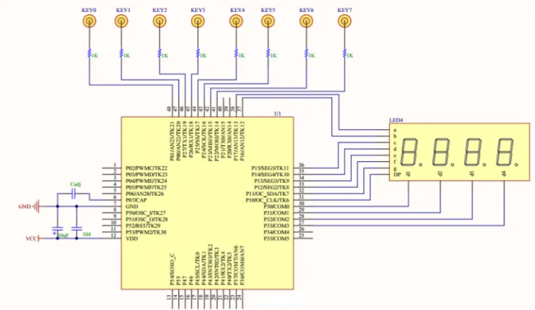
Note: Cadj is the reference capacitor.
Selection of matching resistor and reference capacitor Cadj
Place the matching resistor as close as possible to the touch-chip pin to improve interference immunity. Recommended resistance is 1 kΩ–2 kΩ, default 1.5 kΩ. Place the reference capacitor Cadj as close as possible to the MCU pin and ground. Use an NPO capacitor with low temperature coefficient; capacitance 5.6 nF–22 nF, recommended 10 nF. Position the touch chip near the center of all TouchPads so each TouchPad has a similar distance to the chip pins, which helps reduce touch variation.
Touch routing design requirements
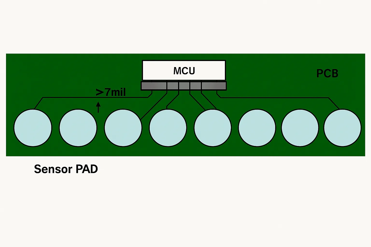
Route TKline from the TouchPad to the MCU touch pin as short and narrow as possible (recommended 7–10 mil) to ensure signal stability. Maintain spacing between TKlines at least twice the trace width.
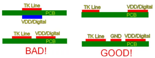
Avoid placing VDD or digital signal traces directly above or below a TKline.
If TKline and VDD/digital traces are on the same layer, keep the spacing greater than four times the trace width.
If board area constraints force TKlines and other signal traces onto the same layer and close together, place a GND trace between them; the GND trace width should be at least twice the TKline width.
Touch routing illustration
When routing multiple keys, make TKline lengths from each TouchPad to the MCU touch pins as equal as possible. In practice, traces contribute parasitic capacitance; differing trace lengths can cause inconsistent sensed capacitance across keys.
Ideal layout
Keep channel traces for individual TouchPads spaced well apart and away from other components and traces, especially high-frequency communication lines such as I2C, SPI, or UART. If crossing is unavoidable, route the two signals perpendicular to each other and avoid parallel routing.
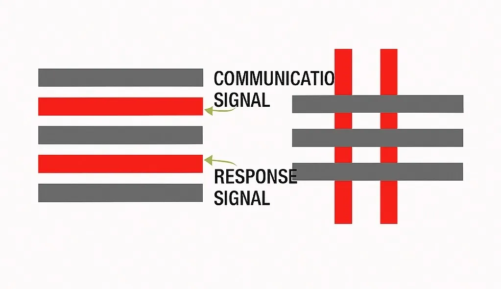
Handling of touch channel traces and communication traces on different layers
TouchPad design
TouchPads can be implemented using external copper foil, metal pieces, springs, conductive foam, or similar materials. For PCB copper foil, common shapes are square, circular, or custom light shapes. Typical TouchPad area ranges from 8 mm × 8 mm to 15 mm × 15 mm; required area varies with panel thickness. If a hole is cut in the TouchPad or an LED is placed, increase the TouchPad area.
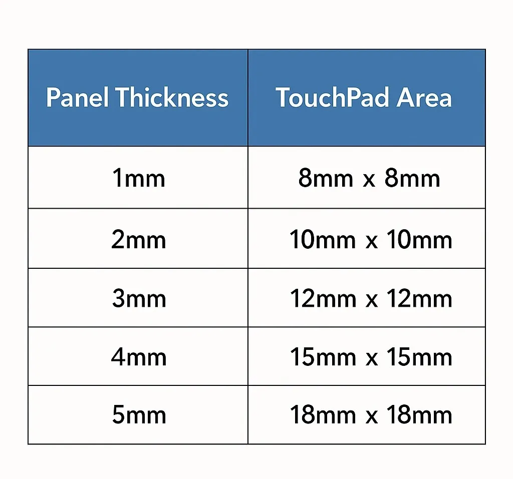
Panel thickness versus touch pad area
Ground pour
If there are no major interference sources on the front or back of the touch area, and the board is separated from other power boards by more than 5 mm, the back side can omit a ground pour.
If performing ground pour, to minimize parasitic capacitance, apply about 40% pour on the touch key layer (touch key layer grid size = 24 mil, track width = 8 mil) and 60%–80% pour on non-touch layers (grid size = 14 mil, track width = 8 mil), as shown below.
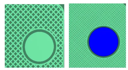
Illustration of top-layer and bottom-layer ground pour for keys
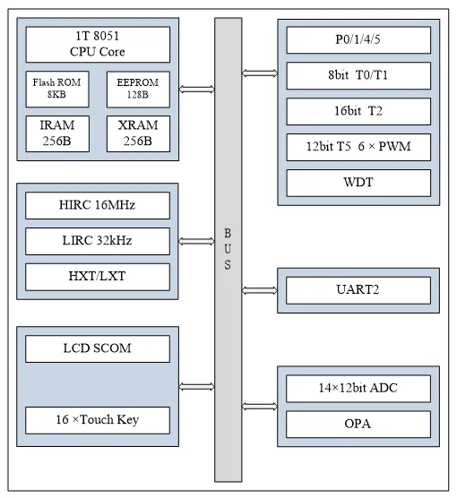
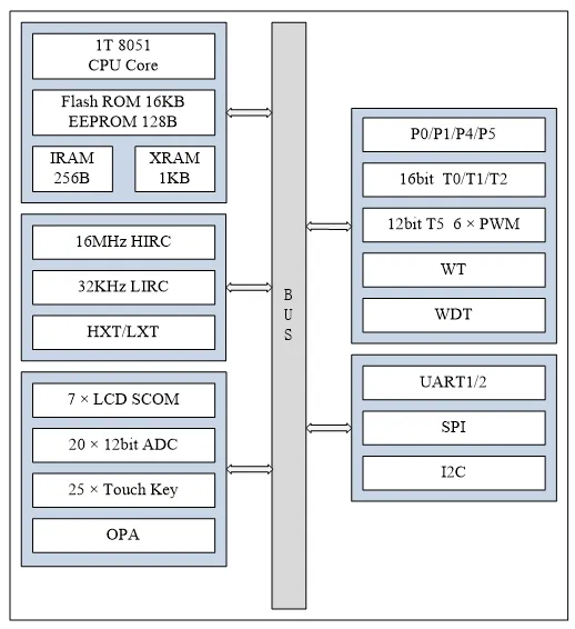
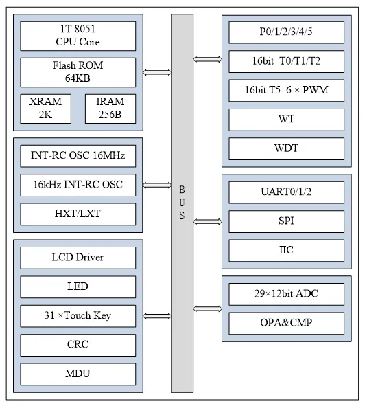
AiP8F32XX product overview
Internal block diagram
Summary
Capacitive touch keys are widely used. The AiP8F32XX MCU family provides many touch ports suitable for multi-key touch scenarios and integrates peripherals such as AD, LED, LCD, I2C, SPI, and UART, offering broad functionality for various applications.