 ALLPCB


Introduction
In PCB assembly, selecting the appropriate resistor technology plays a critical role in achieving reliable performance and efficient manufacturing. Through hole resistors and surface mount resistors, often referred to as SMD resistors, represent two primary mounting methods that engineers must evaluate during component selection. Each approach offers distinct advantages depending on the application's demands, such as power requirements, board density, and environmental conditions. Understanding the differences in resistor mounting helps optimize designs for cost, reliability, and production scalability. This article compares through hole resistors and surface mount resistors, providing practical guidance for electrical engineers involved in PCB assembly processes.

Understanding Through-Hole Resistors
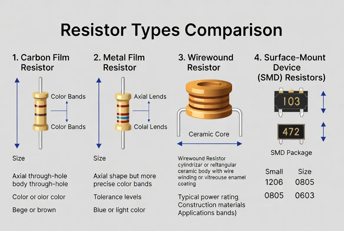
Through hole resistors feature axial leads that pass through drilled holes in the PCB and are soldered on the opposite side. This mounting method provides strong mechanical support, making it suitable for applications where components face mechanical stress or vibration. Engineers often choose through hole resistors for high-power dissipation needs because they offer larger surface areas for heat transfer and robust connections. The assembly process typically involves wave soldering, where the PCB passes over a molten solder wave after component insertion. This technique ensures reliable joints but requires precise hole sizing and lead forming to avoid defects like bridging or insufficient fill.
IPC-7251 outlines the generic requirements for through-hole design and land pattern standards, emphasizing proper pad dimensions to achieve consistent solder joints. Through hole resistors excel in prototyping stages due to their ease of hand soldering and replacement. However, they occupy more board real estate, limiting their use in high-density designs. Common challenges include lead coplanarity issues, which can lead to open joints if not addressed during insertion.
Exploring Surface Mount Resistors (SMD Resistors)
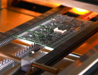
Surface mount resistors, or SMD resistors, adhere directly to the PCB surface using solder paste and reflow soldering. These components come in compact packages like 0603 or 0805, enabling higher component density on the board. SMD resistors support automated pick-and-place assembly, which accelerates PCB assembly and reduces labor costs in high-volume production. Their flat design minimizes height profiles, ideal for slim enclosures or stacked boards. Thermal management relies on pad design and board copper planes, as these resistors have limited mass for heat sinking.
IPC-7351 provides guidelines for surface mount land patterns, ensuring optimal solder paste application and joint formation. Engineers appreciate SMD resistors for signal integrity in high-frequency circuits, where shorter lead lengths reduce parasitic inductance. Despite their advantages, SMD resistors demand careful handling to prevent damage from electrostatic discharge or mechanical stress during assembly. Reflow profiles must align with component tolerances to avoid tombstoning or bridging defects.
Key Differences Between Through-Hole and Surface Mount Resistors
The primary distinction lies in physical mounting and assembly compatibility. Through hole resistors require plated-through holes, increasing fabrication complexity and cost for multilayer boards. In contrast, SMD resistors use surface pads, simplifying routing and allowing double-sided population. Power handling favors through hole types, which can dissipate watts of power via larger bodies, while SMD resistors typically manage milliwatts unless specialized power variants are selected.
Reliability under mechanical stress tilts toward through hole resistors due to their interlocking leads, providing superior vibration resistance. SMD resistors, secured by solder fillets, perform well in controlled environments but may need underfill or conformal coating for harsh conditions. Cost analysis reveals SMD's edge in volume production through automation, whereas through hole suits low-volume or repairable designs.
- Size and Density: Through-hole — larger footprint, lower density; SMD — compact, high density.
- Power Dissipation: Through-hole — high (watts); SMD — low to medium (milliwatts).
- Assembly Method: Through-hole — manual/wave soldering; SMD — automated reflow.
- Mechanical Strength: Through-hole — excellent; SMD — good with proper design.
- Repairability: Through-hole — easy; SMD — challenging.
- Cost in High Volume: Through-hole — higher; SMD — lower.
J-STD-001 specifies requirements for soldered electrical assemblies, covering criteria for both technologies to ensure joint integrity. This list aids component selection by highlighting trade-offs in resistor mounting strategies.
Factors Influencing Component Selection
Engineers base resistor mounting choices on several practical factors. Board space constraints often drive SMD adoption, as these resistors enable finer pitch layouts and multilayer stacking. Power requirements dictate through hole use in power supplies or amplifiers, where heat dissipation prevents derating. Environmental factors, such as temperature cycling or humidity, influence selection; through hole offers better compliance with mechanical shock per assembly standards.
Manufacturing capabilities play a key role in PCB assembly decisions. Facilities equipped for mixed-technology lines handle both seamlessly, but pure SMD lines optimize throughput. Signal integrity considerations favor SMD for RF applications due to minimized parasitics. Cost modeling includes not just component price but tooling, testing, and yield impacts.
During design reviews, simulate thermal performance to validate choices. Oversized pads for SMD improve heat spreading, while annular rings for through hole ensure barrel fill. Compliance with IPC-A-610 acceptability criteria verifies post-assembly quality, focusing on solder fillet geometry and voiding limits.
Best Practices for PCB Assembly and Troubleshooting
For through hole resistor assembly, pre-form leads to maintain standoff and prevent solder wicking that impairs heat transfer. Use selective wave soldering for mixed boards to avoid disturbing SMD components. Inspect for minimum hole fill, typically 75% per standards, and clip leads flush without damaging traces.
SMD resistor placement demands precise stencil apertures to control solder paste volume, mitigating defects like insufficient reflow. Profile ovens with ramp-soak-reflow-cool phases matching JEDEC moisture sensitivity levels. Post-reflow, AOI checks voids or bridges, with rework using hot air for isolated fixes.
Common troubleshooting includes tombstoning in SMD, often from uneven heating; balance paste and profile adjustments resolve it. For through hole, bent leads cause opens; automated inserters with vision systems prevent this. Hybrid designs benefit from fiducials for alignment. Document processes to repeat yields above 99%.
In high-reliability applications, qualify resistors via thermal cycling and vibration tests aligned with industry practices. Conformal coatings protect SMD joints from creepage in humid environments.
Conclusion
Choosing between through hole resistors and surface mount resistors hinges on balancing density, power, reliability, and manufacturability in PCB assembly. Through hole excels in rugged, high-power scenarios, while SMD drives compact, high-volume designs. Practical component selection integrates these with assembly capabilities and standards compliance for optimal outcomes. Engineers gain efficiency by simulating trade-offs early and adhering to proven practices. Ultimately, the right resistor mounting enhances product longevity and production success.
FAQs
Q1: When should I choose a through hole resistor over an SMD resistor in PCB assembly?
A1: Opt for through hole resistors when high power dissipation, mechanical robustness, or easy rework is essential, such as in industrial controls or prototypes. They provide superior heat sinking and vibration resistance compared to SMD resistors. However, reserve them for designs where board space allows, as they increase fabrication costs due to drilled holes. Always verify land patterns per IPC-7251 for reliable joints. This approach suits low-to-medium volume production focused on durability.
Q2: What are the main advantages of surface mount resistors for component selection?
A2: Surface mount resistors enable higher PCB density and automated assembly, reducing costs in high-volume runs. Their compact sizes like 0402 support fine-pitch layouts ideal for consumer electronics. Shorter paths improve high-speed signal performance by lowering inductance. Proper pad design per IPC-7351 ensures strong reflow joints. Select SMD for space-constrained boards prioritizing manufacturability over raw power handling.
Q3: How does resistor mounting affect reliability in harsh environments?
A3: Through hole resistor mounting offers better mechanical anchorage against shock and vibration via leads through the board. SMD resistors rely on solder fillets, benefiting from underfill or edge plating for enhancement. Both must meet J-STD-001 soldering criteria to withstand thermal cycling. Evaluate via accelerated life testing to match application stresses. Hybrid use combines strengths for optimal resilience.
Q4: Can through hole and SMD resistors be mixed in the same PCB assembly?
A4: Yes, mixed-technology PCB assembly is common, using wave soldering for through hole and reflow for SMD resistors. Sequence processes carefully to avoid disturbing placed components. IPC-A-610 defines acceptability for both joint types. This flexibility aids component selection in transitioning designs but requires robust process controls for yield.
References
IPC-7251 — Generic Requirements for Through-Hole Design and Land Pattern Standard. IPC.
IPC-7351 — Generic Requirements for Surface Mount Design and Land Pattern Standard. IPC.
J-STD-001 — Requirements for Soldered Electrical and Electronic Assemblies. IPC, J-STD.
IPC-A-610 — Acceptability of Electronic Assemblies. IPC.





