 ALLPCB


Introduction
Embedding components within PCB laminates represents a significant advancement in electronics packaging, enabling higher component density, reduced parasitics, and improved electrical performance. As designs push toward miniaturization, the choice of laminate material becomes pivotal in ensuring reliability during manufacturing and operation. Engineers must evaluate PCB laminate embedded components compatibility early to avoid issues like delamination or signal degradation. This material selection guide outlines critical PCB material properties that influence success in such designs. Key factors include thermal stability, electrical characteristics, and mechanical integrity, all tailored to the demands of embedding passives or actives. Proper selection aligns with industry standards to meet performance goals in complex multilayer boards.
Why Laminate Selection Matters for Embedded Components
Embedding components integrates resistors, capacitors, or even ICs directly into the laminate stackup, minimizing surface area and enhancing signal integrity. However, this process exposes materials to unique stresses during lamination, drilling, plating, and assembly. Mismatched properties can lead to failures such as cracking or shorts, compromising the entire board. Laminate choice directly impacts yield rates in high-volume production, as it must withstand repeated thermal cycles without degrading. For electric engineers, understanding these interactions ensures designs transition smoothly from prototype to fabrication. Ultimately, strategic material selection supports innovations in high-density interconnects while maintaining cost-effectiveness.
Key PCB Material Properties for Embedding
Thermal Properties
Thermal characteristics dominate laminate performance in embedded designs due to heat generated by closely packed components. Coefficient of thermal expansion (CTE) in x, y, and z axes must closely match those of embedded components to prevent stress-induced cracks during temperature excursions. Glass transition temperature (Tg) should exceed typical reflow profiles to avoid softening, ensuring dimensional stability. Decomposition temperature (Td) provides a margin against oxidation in high-heat processes. Thermal conductivity facilitates heat dissipation from internals, critical for reliability. As defined in IPC-4101, these properties classify laminates for specific applications, guiding engineers toward suitable options.
Z-axis CTE becomes especially vital in multilayer stacks where asymmetry amplifies bowing. Low CTE materials reduce interfacial stresses between the laminate and component terminations. High Tg variants, often above standard levels, support lead-free soldering without phase changes. Engineers evaluate these via differential scanning calorimetry and thermal mechanical analysis per industry methods. Balancing thermal conductivity with insulation prevents hotspots while isolating signals. Factory insights emphasize pre-screening datasheets against process windows for optimal results.
Electrical Properties
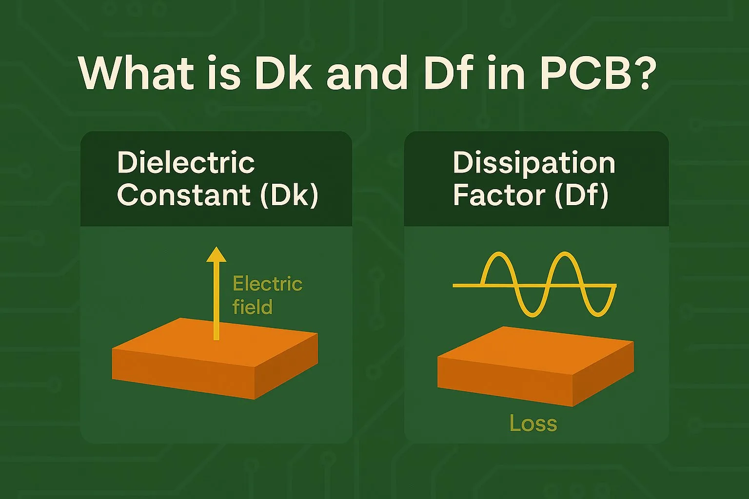
Dielectric constant (Dk) and dissipation factor (Df) dictate signal propagation and loss in embedded circuits. Stable Dk across frequencies minimizes impedance variations, essential for precise timing in high-speed signals. Low Df reduces energy loss as heat, preserving efficiency in dense layouts. Moisture absorption influences these values, so low hygroscopic materials prevent shifts post-fabrication. For embedding, uniform resin distribution ensures consistent properties around components. These metrics, tested per IPC-TM-650 methods, form the basis for qualification in performance specs like IPC-6012.
Frequency-dependent behavior requires laminates with minimal variation in Dk and Df up to operating bands. Embedded components alter local fields, amplifying the need for predictable dielectrics. Engineers prioritize materials with proven stability under bias and temperature. Resin systems with filled composites offer tailored electrical responses. Integration during lamination preserves these traits, avoiding voids that degrade performance.
Mechanical Properties
Mechanical robustness counters warpage and flexure in thin, component-laden boards. High modulus resists deformation under handling or vibration, while flexural strength supports multilayer pressing. Peel strength at copper interfaces prevents delamination during thermal shock. Warpage, often below 0.75% per IPC standards, demands symmetric stackups and low-CTE cores. For embedding, resin flow must fill cavities without trapping air, maintaining planarity.
Thinner laminates amplify sensitivity to copper imbalance, necessitating balanced patterning. Tensile strength ensures integrity during sequential lamination builds. Factory processes like constrained baking mitigate residual stresses. Engineers model these via finite element analysis, correlating to bow and twist limits.
High-Frequency Laminate Considerations for Embedded Designs
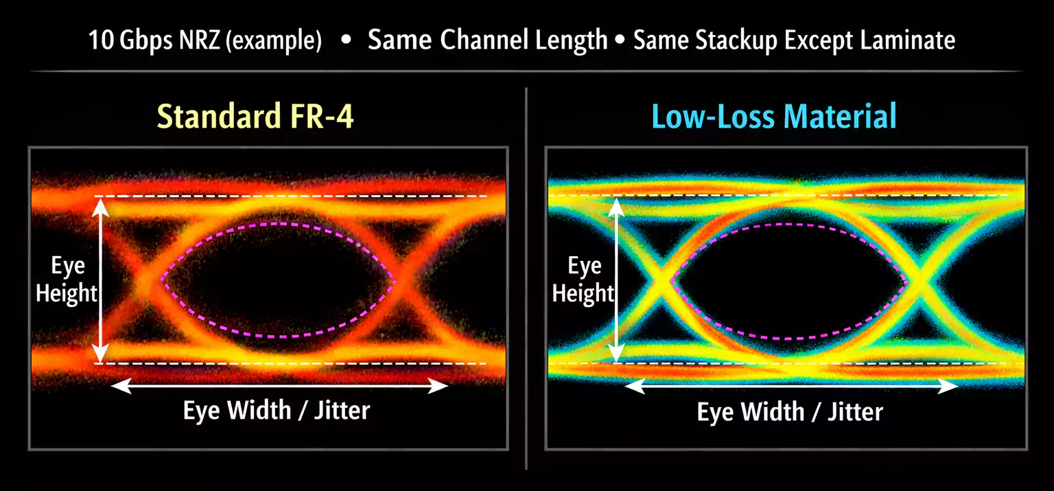
High-frequency laminate materials excel in embedded applications requiring low-loss transmission lines integrated with passives. These laminates feature ultra-low Df and stable Dk, minimizing insertion loss and phase shifts. Embedding inductors or capacitors near RF traces reduces parasitics, but demands materials with consistent isotropy. Ceramic-filled resins provide the necessary performance without PTFE's processing challenges. Signal integrity improves as embedded components shorten paths, yet laminate choice must avoid resonances.
Operating above 1 GHz exposes weaknesses in standard resins, favoring specialized high-frequency laminates. Df below typical thresholds cuts attenuation, vital for multi-gigabit rates. Thermal stability prevents Dk drift in powered states. Sequential build processes integrate these seamlessly with FR-4 hybrids for cost control. Engineers validate via vector network analyzer sweeps on prototypes.
Thermal Management in PCB Materials for Embedding
Thermal conductivity PCB materials address heat trapping inherent to embedded components lacking airflow. Higher in-plane and through-plane conductivity spreads heat evenly, lowering junction temperatures. Filled epoxies or metal-core variants enhance this without compromising insulation. CTE harmony prevents fatigue in vias connecting to surface heatsinks. Power densities in 5G or AI modules necessitate proactive selection.
Convection-limited internals rely on laminate paths to outer layers. Simulations predict hotspots, guiding thickness and filler choices. During lamination, resin cure controls anisotropy. IPC-6012 performance classes set reliability benchmarks under thermal cycling. Mitigation includes vias-in-pad or buried planes, optimized by material traits.
Best Practices for Material Selection Guide
Begin with application requirements: frequency, power, layer count, and component types. Cross-reference datasheets against IPC-4101 slash sheets for matching grades. Prioritize z-CTE below 50 ppm/°C for silicon dies, Tg over 170°C for robustness. Simulate stackups for warpage, iterating laminates until compliant. Hybrid cores blend high-frequency surfaces with thermal bases.
Qualify via test vehicles per J-STD-001 assembly guidelines. Consider resin flow for cavity fill, avoiding underfill needs. Cost-weight performance; standard epoxies suffice for many, reserving exotics for extremes. Collaborate with fabricators on process windows. Document rationale for design reviews.
Common Challenges and Mitigation Strategies
Warpage plagues asymmetric embeds, stemming from CTE gradients and cure shrinkage. Symmetric builds and low-flow prepregs counteract this. Thermal runaway risks demand conductivity over 1 W/mK where possible. Voids from poor wetting cause opens; vacuum lamination resolves. Delamination at interfaces requires plasma cleaning.
IPC-7092 outlines design rules for embedded process implementation, including tolerance stacks. Reliability testing via thermal cycling reveals weaknesses early. Moisture control per JEDEC standards prevents popcorning. Factory-driven adjustments like ramped cures enhance yields.
Conclusion
Selecting the right laminate hinges on balancing thermal, electrical, and mechanical PCB material properties against embedding demands. Prioritizing CTE match, high Tg, low-loss dielectrics, and adequate conductivity ensures reliable high-density boards. High-frequency laminates extend capabilities for advanced signals, while thermal management sustains performance. Adhering to standards like IPC-4101 and IPC-6012 fortifies designs. Engineers gain from systematic evaluation, yielding robust prototypes ready for scale. This approach drives innovation in compact electronics without compromising integrity.
FAQs
Q1: What are the most critical PCB material properties for laminate embedded components?
A1: CTE in all axes, Tg, Dk, Df, and thermal conductivity top the list for PCB laminate embedded components. Matching CTE prevents cracking from thermal mismatch during assembly. High Tg supports reflow soldering, while low Dk/Df ensures signal fidelity. Thermal conductivity dissipates heat from internals effectively. Factory standards like IPC-4101 classify these for reliable selection.
Q2: How does high-frequency laminate impact embedded component designs?
A2: High-frequency laminate reduces losses in designs with embedded passives near RF paths. Low Df minimizes attenuation, stabilizing phase across bands. Stable Dk aids impedance control in dense layouts. These materials handle embedding without degrading performance. Engineers select based on operating frequency for optimal material selection guide outcomes.
Q3: Why is thermal conductivity important in PCB materials for embedding?
A3: Thermal conductivity PCB materials prevent hotspots in embedded components lacking convection. It conducts heat to surface dissipators efficiently. Higher values lower peak temperatures, extending life. Paired with low CTE, it mitigates stresses. Selection focuses on through-plane values for multilayer efficacy.
Q4: How can warpage be minimized in laminates for embedded PCBs?
A4: Symmetric stackups and low-CTE laminates control warpage in PCB laminate embedded components. Balanced copper distribution offsets asymmetry. Constrained lamination and optimized cure profiles reduce bow. Testing per IPC criteria verifies compliance. Material selection guide emphasizes modulus and flow control.
References
IPC-4101 — Specification for Base Materials for Rigid and Multilayer Printed Boards. IPC.
IPC-6012E — Qualification and Performance Specification for Rigid Printed Boards. IPC, 2015.
IPC-7092 — Design and Assembly Process Implementation for Embedded Components. IPC.
J-STD-001G — Requirements for Soldered Electrical and Electronic Assemblies. IPC/JEDEC, 2017.


