 ALLPCB


Experiment name
Nonlinear ultrasonic testing
Research focus
RTM textile composites were used as the inspection target. Nonlinear ultrasonic methods were applied to characterize porosity defects in RTM composites. By measuring nonlinear feature parameters, the study aimed to achieve an initial quantitative characterization of porosity in RTM textile composites.
Objective
Verify the basic requirements of a nonlinear ultrasonic system and several nonlinear ultrasonic experimental methods. For RTM textile composite porosity defects, characterize the nonlinear response of the ultrasonic signal and design a finite-amplitude nonlinear ultrasonic test system for detection.
Test equipment
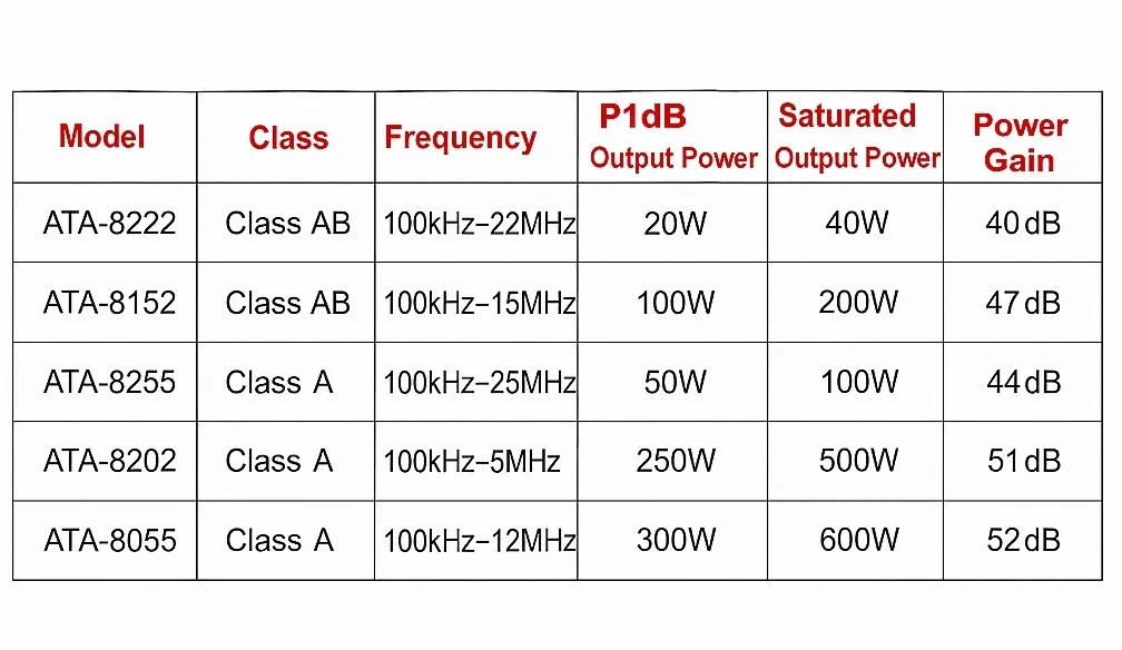
The system included an ATA-8202 RF power amplifier, a digital storage oscilloscope, transmitting and receiving piezoelectric sensors, a computer, and fixtures.
Experimental procedure
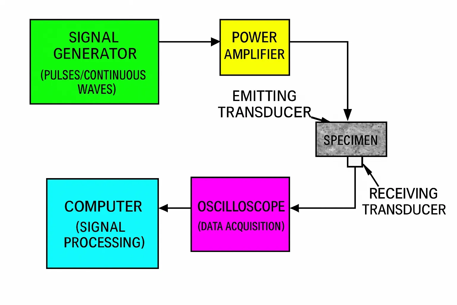
The nonlinear ultrasonic system used a through-transmission approach with broadband reception, measuring amplitudes of the fundamental, second, and third harmonics. A signal generator produced sinusoidal pulse trains, which were amplified by the power amplifier to drive the transmitting piezoelectric transducer at a single frequency. The ultrasonic waves were coupled into the test material. Large-amplitude ultrasound interacts with lattice distortions, microcracks, and anharmonicity in the material, producing strong nonlinear distortion in the transmitted waves. A receiving transducer on the opposite side collected the nonlinear ultrasonic signal. The received signal was processed in MATLAB using a fast Fourier transform to obtain the amplitudes of the fundamental and second harmonic, and the high-order relative nonlinearity coefficient of the material was calculated from those values. The system block diagram is shown below:
Excitation waveform selection
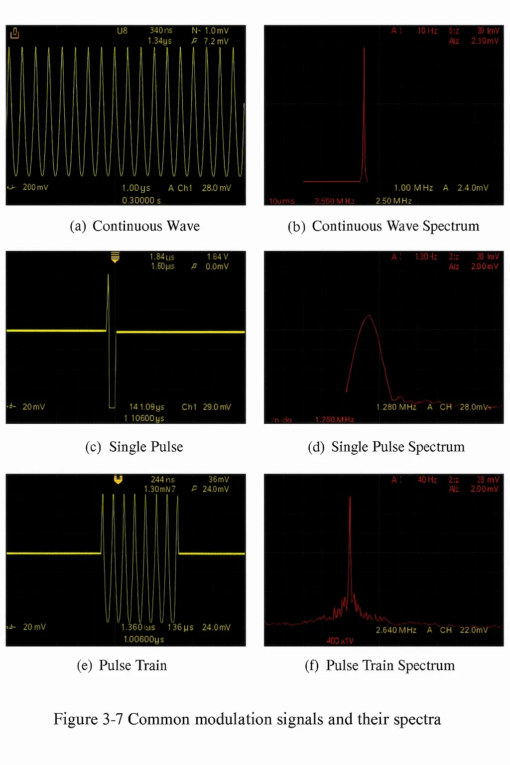
Common excitation waveforms are shown in the figure set. Continuous wave excitation produces a single-frequency ultrasonic wave. Since nonlinear ultrasonic detection is analyzed mainly in the frequency domain, frequency components in the excitation signal significantly affect results. Ensuring a single frequency component is therefore a prerequisite for nonlinear ultrasonic testing. However, producing high-power continuous waves can be difficult, and axial resolution under continuous wave excitation is low.
Single-pulse excitation provides high amplitude and high axial resolution, but the pulse has a wide frequency range and may introduce frequency components other than the fundamental at the transmitter. Different frequency components interact with microdefects differently, generating nonlinear responses that are not intrinsic to the material and reducing measurement accuracy. Additionally, the short interaction time under single-pulse excitation makes it difficult to generate strong nonlinear effects. For these reasons, this experiment used a pulse-train mode as the excitation signal. The pulse-train mode provides higher output power with relatively narrow frequency content, which is widely used in nonlinear ultrasonic detection.
Pulse-train parameters
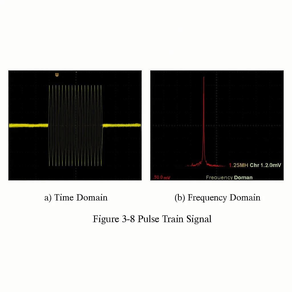
In pulse-train mode, the number of cycles per burst is adjustable; more cycles produce a narrower frequency component. Considering the specimen and available transducers, this experiment used a 2.25 MHz pulse train with 30 cycles. The figure shows the time-domain waveform for a 20-cycle pulse train used in the experiment and its FFT. The frequency-domain plot shows no second-harmonic component at the 5 MHz harmonic location, indicating the excitation was sufficiently single-frequency and did not affect the test results.
Experimental results
Transmit transducer selection
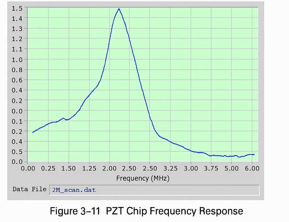
A narrowband PZT element with a center frequency of 2.25 MHz was selected as the transmitting transducer. A bare PZT wafer was used because, compared with commercial transducers, an unbacked wafer vibrates freely without the influence of a damping block or other components, reducing nonlinear interference introduced by the transducer. The PZT element photo and its initial vibration waveform under square-wave excitation are shown below. The frequency sweep indicates a center frequency of 2.25 MHz with a narrow bandwidth, producing predominantly single-frequency ultrasonic output suitable for nonlinear ultrasonic emission.
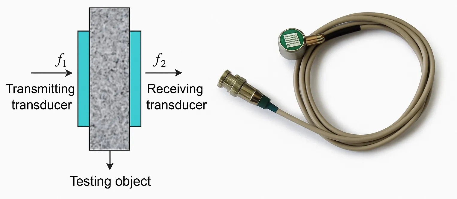
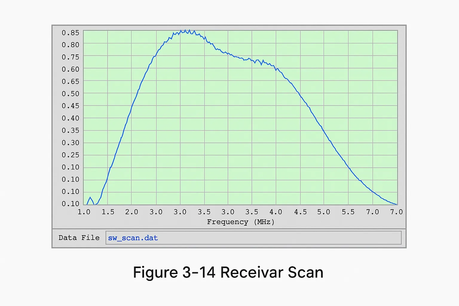
Receive transducer selection
A broadband reception approach was chosen: a wideband transducer receives both the fundamental and higher harmonics, providing consistent and synchronous responses for both. Based on this, an Olympus Panametrics commercial probe, model Olympus C109, was selected; its center frequency is 4 MHz. The probe photo and frequency sweep are shown; the probe responds across roughly 1.5 MHz to 6.5 MHz, facilitating observation of second and third harmonics.
Summary
The experiment validated basic requirements for a nonlinear ultrasonic system and compared several experimental methods. For RTM textile composite porosity defects, a finite-amplitude nonlinear ultrasonic detection system was designed. Potential sources of nonlinear interference were analyzed, and appropriate excitation waveforms and transmit/receive transducers were selected to ensure system reliability.
Credits
Experimental materials were compiled by Xi'an Antai Electronics. Aigtek is a high-tech company in China specializing in research, production, and sales of test instruments, focusing on high-voltage amplifiers, voltage amplifiers, power amplifier modules, and high-precision current sources.


