ALLPCB


Overview
Thermal cameras can detect heat as well as visible light, making them useful for finding hidden energy losses, locating overheated components, and operating in darkness. Their high value in maintenance and diagnostics is well known, but cost can be a barrier. This project demonstrates a lower-cost DIY thermal camera using affordable components. Candidate sensors considered were Panasonic AMG8833, Melexis MLX90640, and MLX90641. The AMG8833 is the cheapest but only provides 8x8 resolution, while the MLX90640 offers 32x24 and the MLX90641 16x12. The MLX90640 provides the best resolution in this price range, so it was selected for this DIY thermal camera.
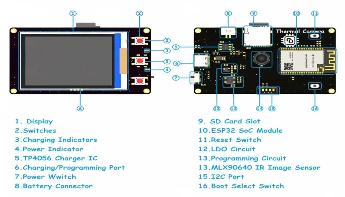
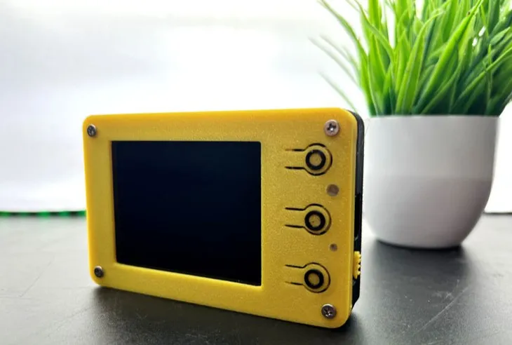
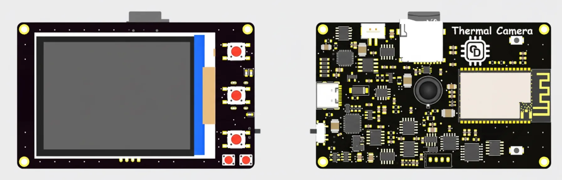
Below is the assembled DIY thermal camera:
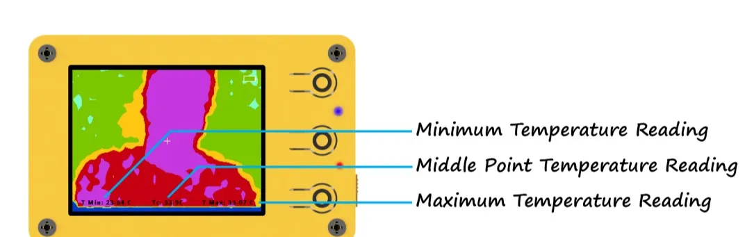
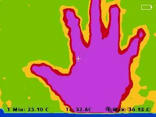
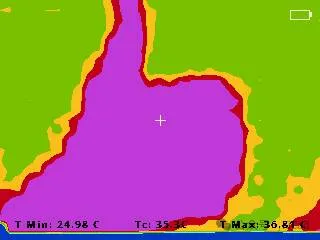
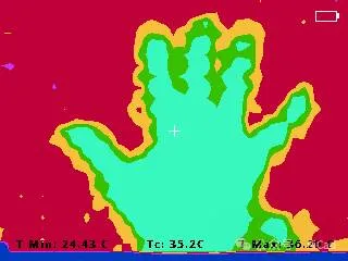
This is the main screen interface. The main screen shows the thermal image along with minimum, maximum, and center-point temperatures and a battery icon.
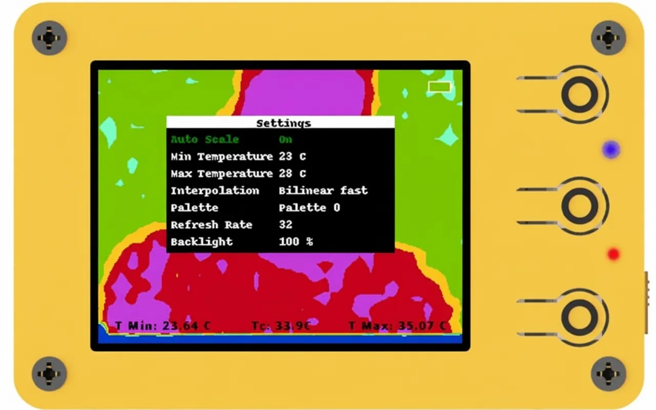
The image below shows the device settings screen. There are seven options. The selected option is shown in green text, while others are white. Short press the middle button to change the selection. Adjust the selected option's value with the up/+ and down/- buttons.
Sample thermal images:

Hardware Features
- Image sensor resolution: 32x24.
- Sensor field of view (FoV): 55° x 35°.
- Temperature measurement range: -40 to 300°C.
- Operating temperature range: -40 to 85°C.
- Adjustable refresh rate: 4 Hz to 32 Hz.
- 10 color palettes.
- 5 interpolation modes.
- User-friendly graphical interface.
- 2.4" TFT display, resolution 320x240.
- Save thermal images to an SD card.
- Built-in battery and charging circuit.
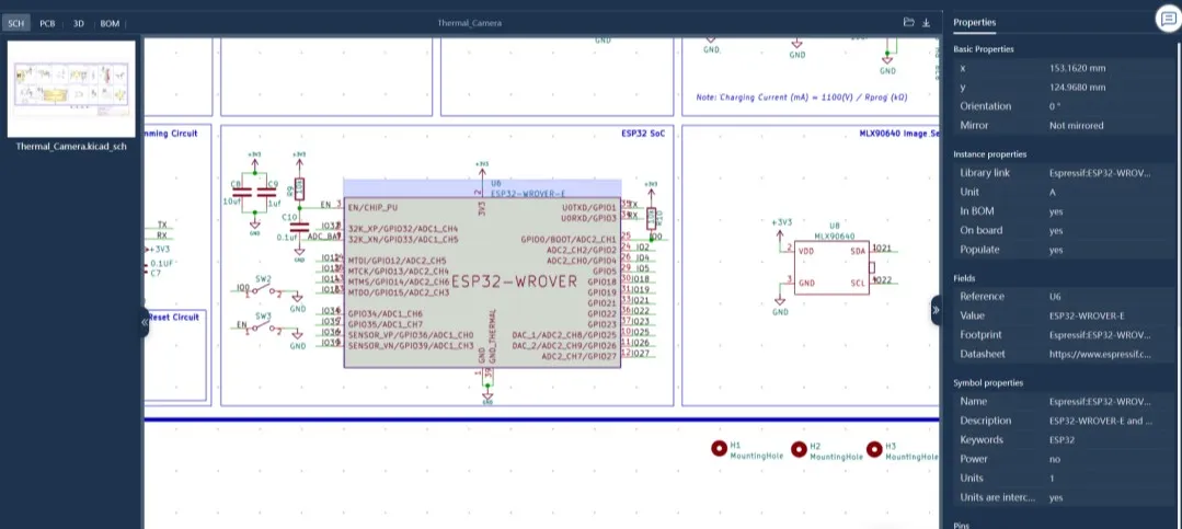
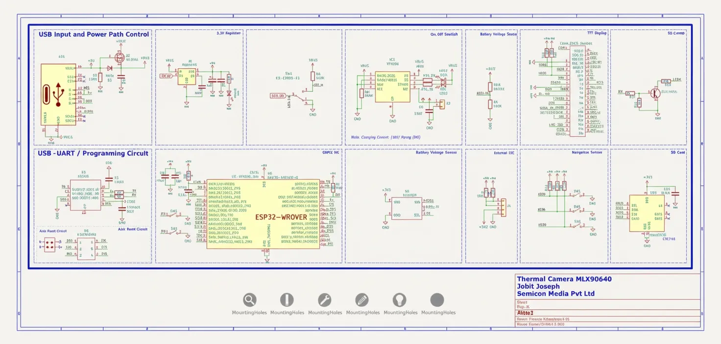
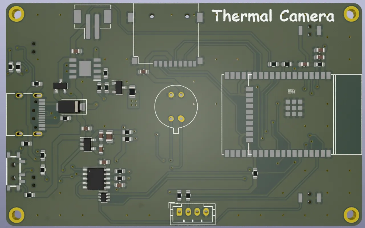
Circuit Design
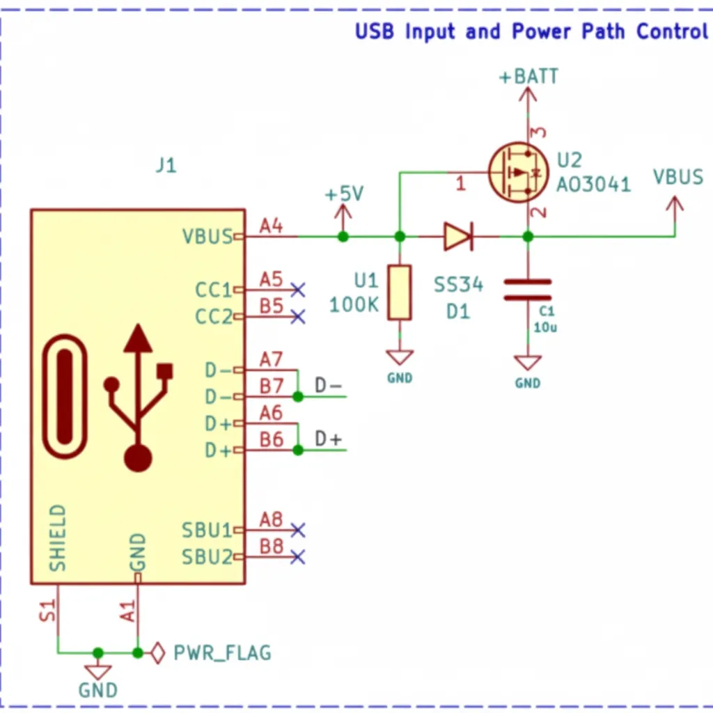
First, an overview of the schematic is presented for clarity. A USB Type-C connector is used for charging and firmware programming. The USB power input is routed through a power-path controller built with a P-channel MOSFET (U2) and a diode (D1). When USB power is present the device runs from USB power and charges the internal battery; when USB is removed the device automatically switches to battery power.
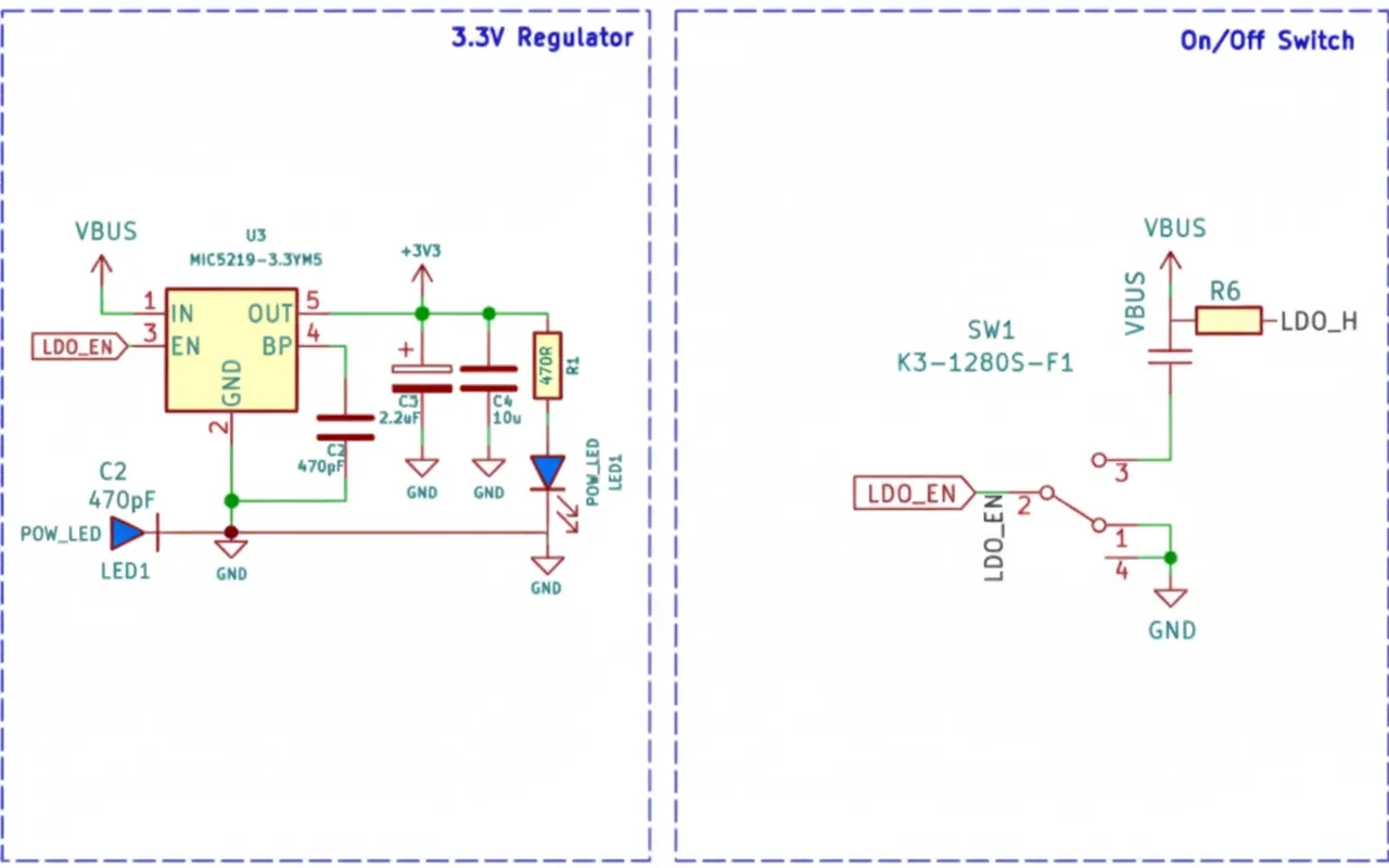
For voltage regulation, a Microchip MIC5219 3.3V LDO is used, capable of supplying up to 500 mA and featuring a low dropout of about 500 mV at full load. The enable pin of the MIC5219 is tied to a slide switch with a pull-up resistor. This switch is used to turn the thermal camera on and off. When the enable pin is pulled low, the LDO shuts down and most of the device is powered off, except for the battery charging section.
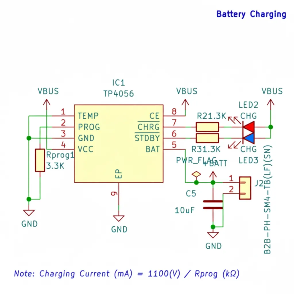
The battery charger is a TP4056 charge controller with a maximum charge current of 1 A. Battery voltage is monitored with a simple resistive divider to scale the voltage to a safe measurement range.
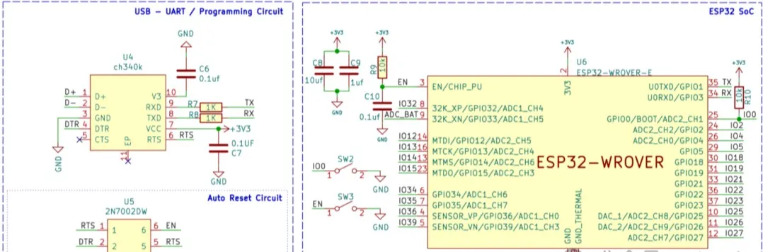
Next is the ESP32 SoC, the programming circuit, and the MLX90640 infrared sensor array. The programming interface uses a CH340K USB-to-UART controller and an ON Semiconductor 2N7002DW dual N-channel MOSFET. The CH340K was chosen for its small size and low cost. The MOSFETs form an auto-reset circuit for the ESP32 to avoid manual toggling during programming. Although auto-reset works reliably, manual boot and reset buttons were also included. Surrounding circuitry for the ESP32 is standard, with bypass capacitors and pull-up resistors where needed.
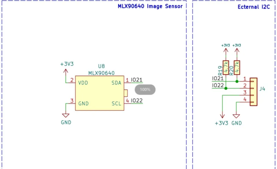
The image sensor is soldered directly to the PCB for compactness. The sensor communicates with the SoC over I2C and requires only four pins including power and ground. If a sensor module is preferred, or additional I2C devices are needed, an I2C connector is provided on the PCB.
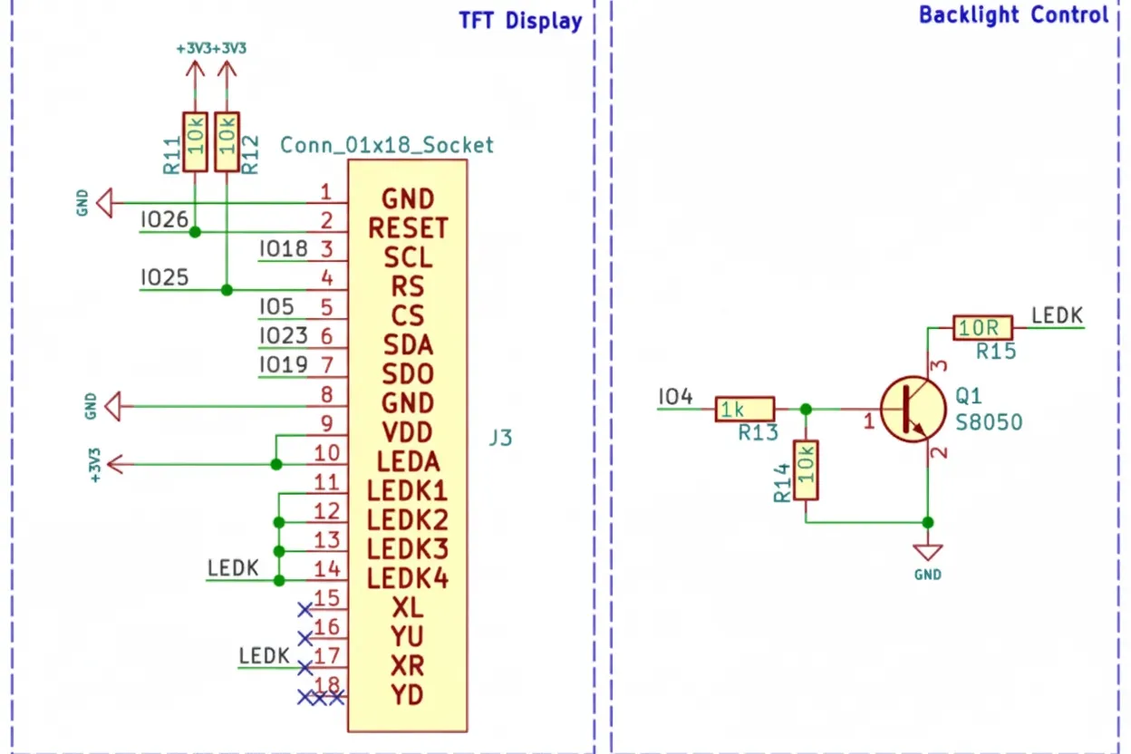
The final section contains the TFT display, navigation buttons, and Micro SD slot. The display is a 2.4" TFT with 320x240 resolution driven by an ILI9341 driver. It connects to the ESP32 via SPI and supports up to 65 MHz SPI clock. The display is soldered directly to the PCB. Backlight control uses an S8050 transistor and can be PWM-driven to adjust brightness. The display is connected to the ESP32 VSPI interface, while the Micro SD slot is connected to the HSPI interface so the ESP32 can access both if required.
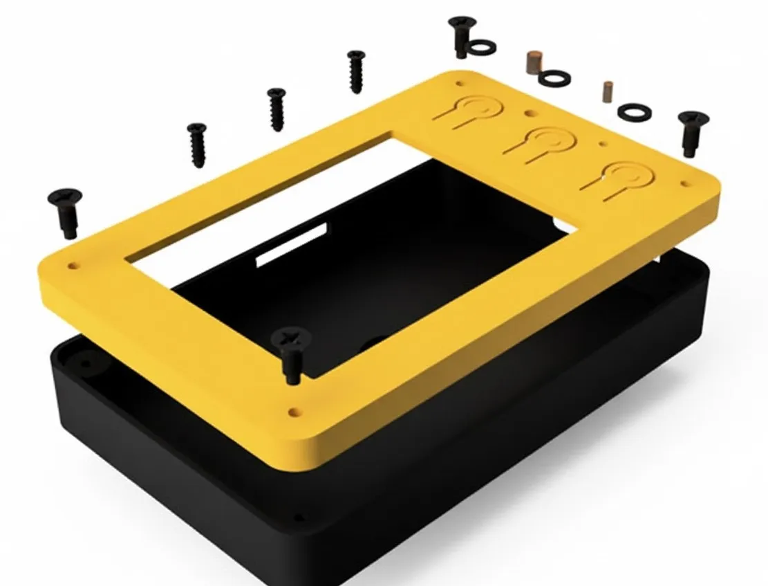
3D Printed Parts
Assembled device:
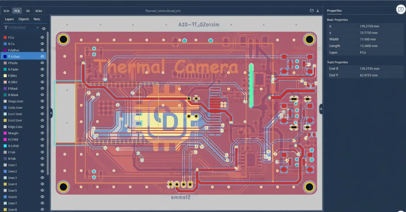
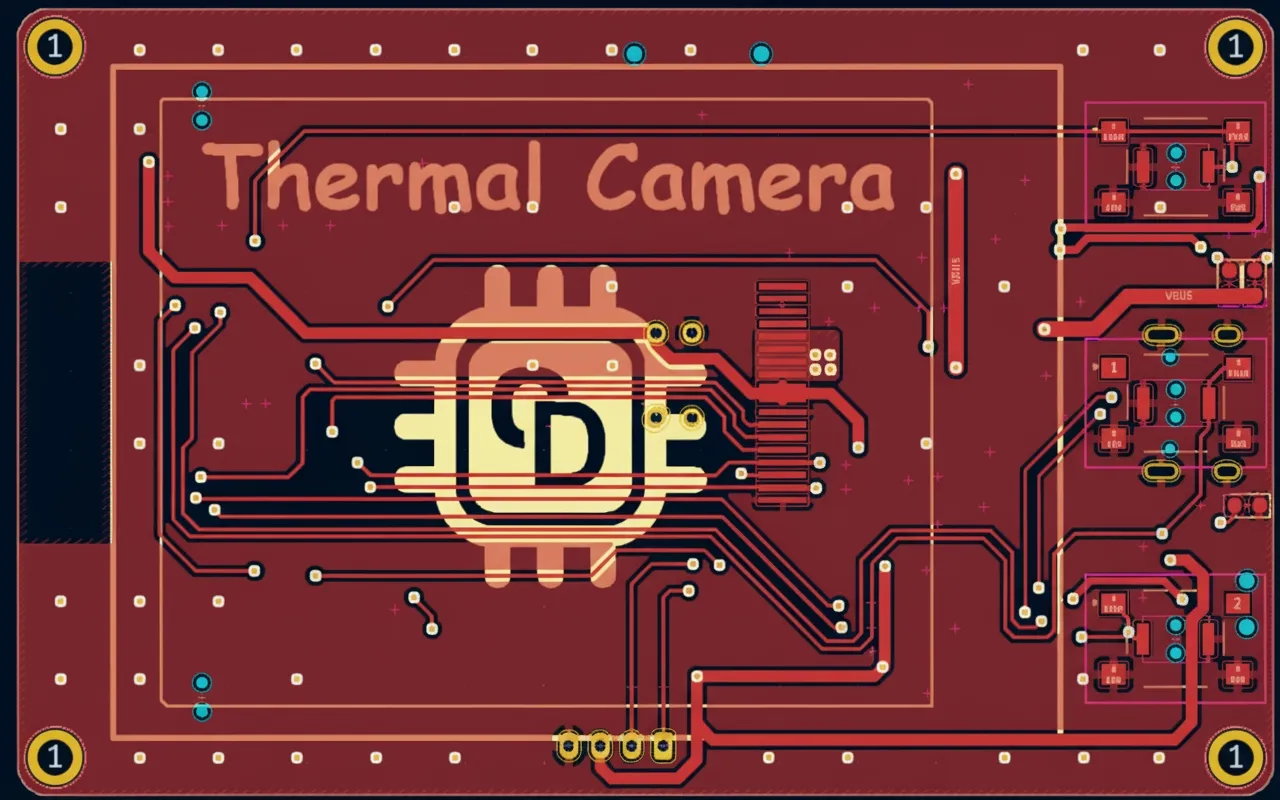
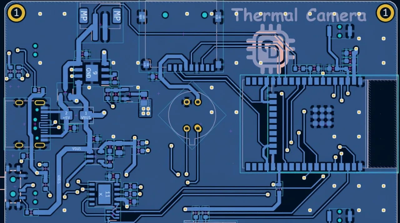
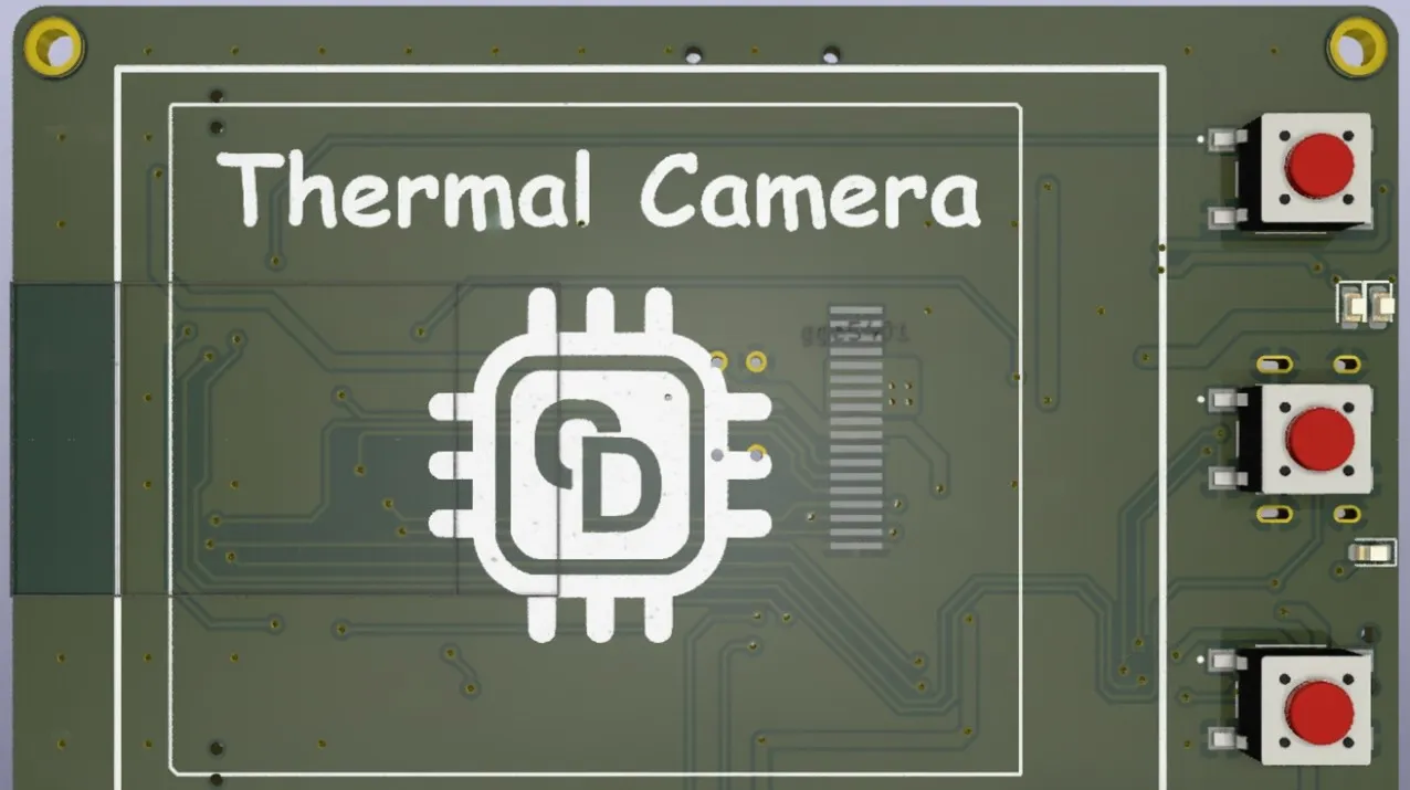
Schematics & PCB
Resources
Designs were created with KiCad. The project files include schematics, PCB layout, 3D models, and BOM. An online viewer supports inspecting design elements and component attributes.