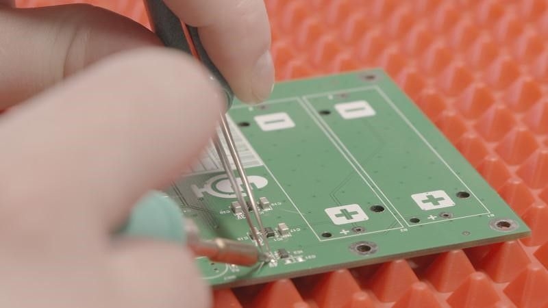
If you're looking to master prototyping and validation for SMT (Surface Mount Technology) and Through-Hole hybrid PCB designs, you've come to the right place. This guide will walk you through proven techniques to ensure your hybrid boards are functional, reliable, and ready for production. Whether you're optimizing for "SMT techniques validation," exploring "Through-Hole hybrid" designs, or focusing on "prototyping and validation," we'll cover the essential steps to achieve success in your electronics projects.
In this comprehensive blog, we'll dive deep into the world of hybrid PCB designs, blending SMT and Through-Hole technologies. You'll learn the best practices for prototyping, the critical validation methods to test your designs, and how to address common challenges. Let’s get started with actionable insights tailored for engineers and designers in the electronics manufacturing space.
Understanding SMT and Through-Hole Hybrids in PCB Design
Hybrid PCB designs combine the strengths of SMT and Through-Hole Technology (THT). SMT allows for smaller, densely packed components, making it ideal for compact, high-speed electronics. On the other hand, THT provides robust mechanical strength and is often used for components that endure high stress or require manual assembly, such as connectors and large capacitors.
Using a hybrid approach, you can leverage the compact nature of SMT for most components while incorporating THT for specific parts that need durability. This combination is common in applications like power electronics, automotive systems, and industrial controls, where both performance and reliability are critical.
Why Prototyping Matters for Hybrid Designs
Prototyping is the foundation of any successful PCB project. For hybrid designs, it’s even more crucial due to the mix of assembly techniques and potential compatibility issues. A prototype helps you identify design flaws, test functionality, and ensure that both SMT and THT components work seamlessly together before moving to full-scale production.
Effective prototyping saves time and reduces costs by catching errors early. For instance, mismatched thermal profiles during soldering can lead to component failure, and a prototype allows you to test soldering processes for both SMT and THT parts. By focusing on "prototyping and validation," you can refine your design to meet performance standards and avoid costly rework later.
Key Prototyping Techniques for SMT and Through-Hole Hybrids
Creating a prototype for a hybrid PCB requires careful planning and execution. Below are some proven techniques to help you build a reliable prototype.
1. Design with Assembly in Mind
Start by designing your PCB layout to accommodate both SMT and THT components. Use design software to ensure proper spacing between components, especially around THT leads, which require drilled holes. Keep SMT components on one side of the board if possible to simplify automated assembly, while THT parts can be placed on the opposite side for manual soldering.
For example, maintain a clearance of at least 0.5 mm between SMT pads and THT holes to prevent solder bridging. Additionally, consider the thermal impact of soldering processes, as SMT components are sensitive to high temperatures often used in THT wave soldering.
2. Use Modular Testing Boards
Build modular prototypes that allow you to test specific sections of your design independently. For instance, create a small test board for power supply circuits with THT components and another for high-frequency SMT circuits. This approach helps isolate issues and makes it easier to validate each part of the hybrid design.
3. Select the Right Materials
Choose a PCB substrate that supports both SMT and THT assembly processes. FR-4 is a common choice due to its durability and compatibility with high-temperature soldering. Ensure the board thickness (typically 1.6 mm) can handle the mechanical stress of THT components while supporting the fine traces needed for SMT.
4. Start with Small Batches
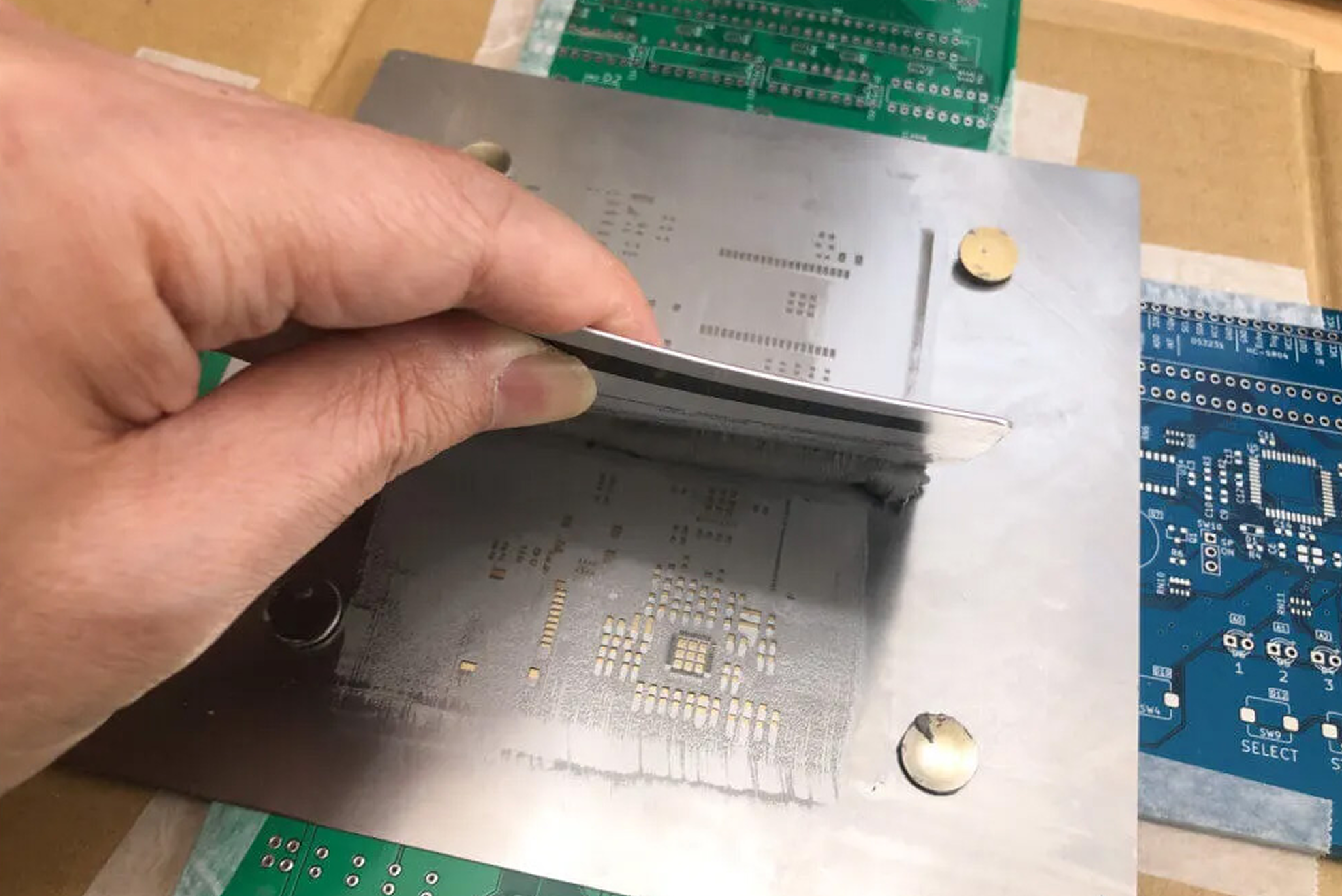
Produce a small batch of prototypes (e.g., 5-10 units) to test different assembly variations. This allows you to experiment with SMT reflow soldering profiles and THT soldering techniques without committing to a large production run. Small batches also help you assess component placement accuracy and identify potential manufacturing issues.
Validation Techniques for SMT and Through-Hole Hybrids
Once your prototype is built, validation ensures that the design meets performance, reliability, and manufacturing standards. Here are key methods for "SMT techniques validation" and overall hybrid PCB testing.
1. Visual and Automated Inspection
Begin with a thorough visual inspection to check for soldering defects, such as cold joints in THT components or tombstoning in SMT parts. Use magnifying tools or microscopes to examine small SMT components with pitches as fine as 0.4 mm.
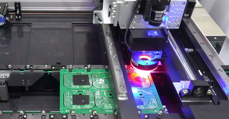
For larger batches, Automated Optical Inspection (AOI) systems can scan the board for defects in both SMT and THT assembly. AOI is particularly useful for detecting misaligned SMT components or insufficient solder on THT leads.
2. Electrical Testing for Functionality
Perform in-circuit testing (ICT) to verify the electrical functionality of your hybrid PCB. ICT checks for open circuits, short circuits, and incorrect component values. For instance, ensure that a THT power connector delivers the expected voltage (e.g., 12V) and that SMT ICs operate within their specified frequency range (e.g., 100 MHz).
Additionally, use a multimeter to measure impedance across critical paths. For high-speed SMT circuits, aim for controlled impedance values, such as 50 ohms, to minimize signal loss.
3. Thermal and Environmental Testing
Hybrid designs often face varied operating conditions, so thermal and environmental testing is essential. Use a thermal chamber to simulate temperature ranges (e.g., -40°C to 85°C) and observe how SMT and THT components perform. THT components may handle thermal stress better, but SMT parts could suffer from solder joint cracking if the reflow profile wasn’t optimized.
Environmental tests, such as humidity exposure (e.g., 85% relative humidity), help validate the board’s reliability in harsh conditions. This is critical for applications like automotive or outdoor electronics.
4. Signal Integrity Analysis
For high-speed designs with SMT components, signal integrity is a priority. Use an oscilloscope to measure signal rise times and jitter. For example, a rise time of less than 1 ns is often required for high-speed digital signals to prevent data errors. Ensure that THT connectors don’t introduce excessive noise or crosstalk into the system by placing them away from sensitive SMT signal traces.
5. Mechanical Stress Testing
THT components are often used for their mechanical strength, so test the board under vibration or shock conditions. For instance, simulate a vibration frequency of 10-55 Hz to ensure THT leads remain secure and SMT components don’t detach from the board. This type of validation is vital for industrial or aerospace applications.
Challenges in Prototyping and Validation of Hybrid Designs
While hybrid designs offer numerous benefits, they come with unique challenges. Understanding these obstacles can help you refine your "prototyping and validation" process for better results.
1. Soldering Compatibility Issues
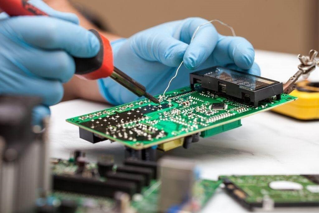
SMT components typically use reflow soldering, while THT parts often require wave soldering or manual soldering. Combining these processes can lead to thermal stress on SMT components during wave soldering. To mitigate this, consider selective soldering for THT parts or use heat-resistant SMT components rated for higher temperatures (e.g., up to 260°C).
2. Component Placement Complexity
Mixing SMT and THT components increases the complexity of component placement. Automated pick-and-place machines handle SMT parts efficiently, but THT components often require manual insertion. Plan your assembly process to minimize errors, such as ensuring THT holes are not obstructed by SMT pads.
3. Cost and Time Constraints
Hybrid designs can be more expensive and time-consuming to prototype due to the dual assembly processes. Minimize costs by optimizing your design for manufacturability and limiting the number of THT components to only those that are necessary for mechanical or electrical reasons.
Best Practices for Successful Hybrid PCB Development
To wrap up, here are some best practices to ensure your hybrid PCB project succeeds during prototyping and validation:
- Collaborate Early with Manufacturers: Work with your assembly team to understand their capabilities for handling hybrid designs. This ensures your design aligns with their equipment and processes.
- Iterate Based on Feedback: Use data from each prototype batch to refine your design. For example, if thermal testing shows SMT solder joint failures, adjust the reflow profile or component selection.
- Document Everything: Keep detailed records of prototyping steps, test results, and design changes. This documentation is invaluable for troubleshooting and scaling to production.
- Prioritize Critical Components: Focus validation efforts on high-risk areas, such as power delivery circuits with THT components or high-speed SMT signal paths.
Conclusion: Mastering Prototyping and Validation for Hybrid PCBs
Prototyping and validation are the cornerstones of creating reliable SMT and Through-Hole hybrid PCB designs. By following the techniques outlined in this guide, you can address the unique challenges of hybrid designs and ensure your boards meet performance and reliability standards. From careful design planning to rigorous "SMT techniques validation" and testing for "Through-Hole hybrid" compatibility, each step brings you closer to a successful product.
Whether you're working on compact consumer electronics or robust industrial systems, a well-executed "prototyping and validation" process is key to avoiding costly errors and achieving manufacturing success. Take these insights, apply them to your next project, and build hybrid PCBs that stand the test of time.
 ALLPCB


