 ALLPCB


Are you a hobbyist struggling with flex PCB trace routing issues? Whether you're dealing with broken traces, cracking on flexible substrates, or figuring out the right trace width for your DIY project, troubleshooting flex PCBs can be a challenge. In this comprehensive guide, we'll walk you through practical solutions for DIY flex PCB trace repair, including bridging broken traces on flex PCBs, using conductive epoxy for flex trace repair, understanding trace width considerations for DIY flex circuits, and tips for avoiding trace cracking on flexible substrates. Let's dive into the details to help you get your projects back on track.
What Are Flex PCBs and Why Do They Pose Unique Challenges?
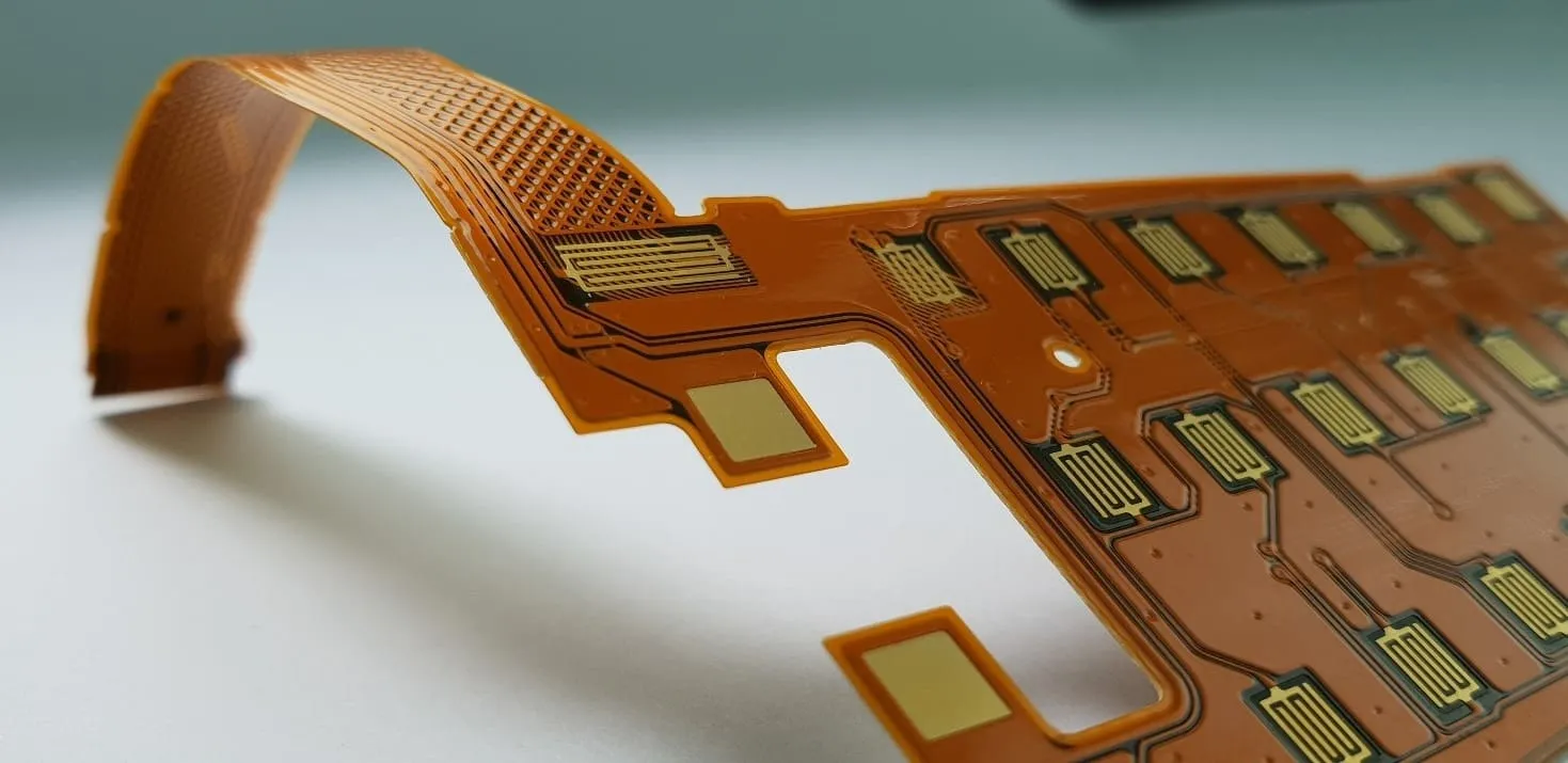
Flexible Printed Circuit Boards (flex PCBs) are a type of circuit board made from flexible materials like polyimide, allowing them to bend and conform to various shapes. They’re widely used in compact electronics, wearables, and medical devices due to their lightweight design and ability to fit into tight spaces. However, their flexibility introduces unique challenges, especially for hobbyists working on DIY projects. Unlike rigid PCBs, flex PCBs are prone to trace cracking, delamination, and damage during handling or repeated bending.
As a hobbyist, you might encounter issues like broken traces from excessive bending or improper routing, which can disrupt signal flow and render your project unusable. Understanding how to troubleshoot and repair these issues is crucial to saving time and money. In the sections below, we'll cover actionable techniques to address these problems step by step.
Common Flex PCB Trace Routing Issues Hobbyists Face
Before diving into solutions, let’s identify the common problems you might encounter with flex PCB trace routing:
- Broken Traces: Repeated bending or physical stress can cause the thin copper traces to snap, interrupting electrical connections.
- Trace Cracking: Improper design or material stress during bending can lead to micro-cracks in traces, causing intermittent signal loss.
- Improper Trace Width: Incorrect trace width can result in overheating or insufficient current-carrying capacity, especially in high-current applications.
- Delamination: The layers of a flex PCB can separate under stress, damaging traces and reducing durability.
These issues often stem from design errors, material limitations, or mishandling during assembly and repair. Let’s explore how to tackle each problem with practical DIY flex PCB trace repair techniques.
Step 1: Diagnosing Broken Traces on Flex PCBs
The first step in troubleshooting is identifying the problem. A broken trace on a flex PCB can cause a complete loss of connectivity between components. To diagnose this issue, follow these steps:
- Visual Inspection: Use a magnifying glass or a microscope to look for visible breaks or cracks in the copper traces. Pay close attention to areas where the PCB bends frequently.
- Continuity Test: Use a multimeter set to continuity mode to check if there’s a break in the circuit. Touch the probes to either end of the suspected trace. If there’s no beep, the trace is broken.
- Flex Testing: Gently bend the PCB near the suspected area while monitoring with the multimeter. If the continuity changes with bending, you’ve likely found a stress-related break.
Once you’ve confirmed a broken trace, the next step is repairing it. This is where bridging broken traces on flex PCBs comes into play.

Step 2: Bridging Broken Traces on Flex PCBs with DIY Methods
Repairing a broken trace on a flex PCB doesn’t require expensive tools. Here are two beginner-friendly methods for bridging broken traces on flex PCBs that you can try at home:
Method 1: Using Conductive Epoxy
One of the most accessible solutions for hobbyists is using conductive epoxy for flex trace repair. Conductive epoxy is a two-part adhesive mixed with conductive particles (like silver) that can form an electrical connection. Here’s how to use it:
- Clean the Area: Use isopropyl alcohol and a cotton swab to clean the broken trace area. Remove any dirt, grease, or oxidation to ensure good adhesion.
- Mix the Epoxy: Follow the manufacturer’s instructions to mix the conductive epoxy. Work quickly, as most epoxies set within minutes.
- Apply Carefully: Use a fine-tip applicator or a toothpick to apply a small amount of epoxy over the break, ensuring it connects both ends of the trace. Avoid applying too much to prevent shorting nearby traces.
- Cure the Epoxy: Let the epoxy cure for the recommended time (usually 24 hours) at room temperature. Some epoxies may require heat for faster curing—check the instructions.
- Test the Repair: Use a multimeter to confirm continuity across the repaired trace.
Note: Conductive epoxy typically has higher resistance than copper (around 0.001 ohms per inch for high-quality products), so it’s best for low-current applications. For high-current traces, consider the next method.
Method 2: Using Thin Wire or Copper Tape
For a more robust repair, you can bridge the broken trace with a thin wire or copper tape:
- Prepare the Trace: Scrape away the protective coating (solder mask) on either side of the break using a fine blade or sandpaper to expose the copper.
- Cut a Bridge: Cut a small piece of thin wire (like 30 AWG) or copper tape to span the break.
- Solder or Adhere: If using wire, solder it to both ends of the trace with a low-temperature soldering iron (around 250°C) to avoid damaging the flex substrate. If using copper tape, apply it with a small amount of conductive adhesive.
- Secure the Repair: Cover the repaired area with a small piece of Kapton tape or liquid electrical tape to protect it from further damage.
- Test: Check continuity with a multimeter to ensure the repair holds.
Both methods are effective for DIY flex PCB trace repair, but choose based on the current requirements and tools you have on hand.
Step 3: Trace Width Considerations for DIY Flex Circuits
When designing or repairing flex PCBs, trace width considerations for DIY flex circuits are critical to ensure functionality and reliability. Trace width determines how much current a trace can carry without overheating or breaking. Here’s what hobbyists need to know:
- Current Carrying Capacity: The width of a trace must match the current it will carry. For example, a 10-mil (0.254 mm) wide trace on a 1 oz copper flex PCB can typically carry around 0.5 amps safely at room temperature. For higher currents, increase the width proportionally.
- Space Constraints: Flex PCBs often have limited space, so traces are narrower than on rigid boards. However, overly narrow traces can overheat or crack under stress. A minimum width of 6-8 mils (0.15-0.2 mm) is recommended for most low-current applications.
- Impedance Control: For high-speed signals (like USB or HDMI), trace width affects impedance. A typical 50-ohm impedance trace on a flex PCB might require a width of 4-6 mils, depending on the substrate thickness and dielectric constant (often around 3.4 for polyimide).
To calculate the appropriate trace width for your project, use online calculators or reference charts specific to flex PCB materials. Always err on the side of wider traces when possible to reduce the risk of overheating or cracking.

Step 4: Avoiding Trace Cracking on Flexible Substrates
One of the biggest challenges with flex PCBs is avoiding trace cracking on flexible substrates. Cracks often form due to repeated bending, sharp corners in trace routing, or improper material selection. Here are some tips to prevent cracking during design and handling:
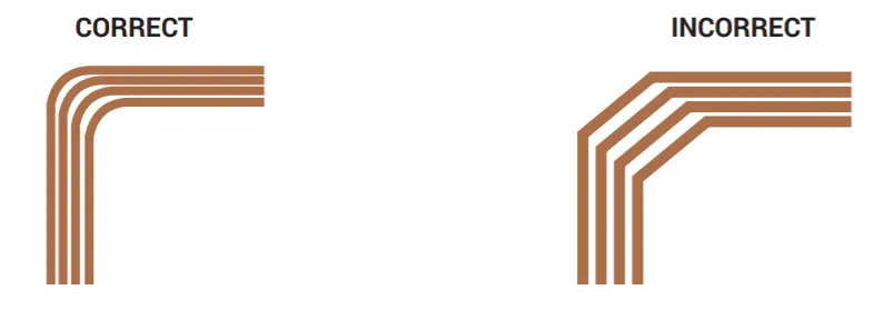
- Use Rounded Corners: Avoid sharp 90-degree turns in your trace routing. Instead, use smooth, curved paths to reduce stress concentration during bending. A minimum bend radius of 3-5 times the trace width is ideal.
- Minimize Bending in Trace Areas: Design your flex PCB so that traces run through areas with minimal bending. Place critical traces in static regions if possible.
- Add Strain Relief: Incorporate strain relief features, like teardrop-shaped pads or wider anchor points, at the transition between rigid and flex areas to distribute stress evenly.
- Handle with Care: When working with flex PCBs, avoid excessive or sharp bending. A bend radius of at least 10 times the board thickness (e.g., 1 mm for a 0.1 mm thick board) helps prevent substrate and trace damage.
- Choose the Right Material: For DIY projects, ensure your flex PCB substrate (like polyimide) is rated for the expected number of bend cycles. Standard polyimide can handle around 10,000-20,000 bends before fatigue sets in.
By following these practices, you can significantly reduce the risk of trace cracking and extend the lifespan of your flex PCB projects.
Additional Tips for Successful Flex PCB Troubleshooting
Beyond the core techniques, here are a few extra tips to help hobbyists succeed with flex PCB projects:
- Protect Repaired Areas: After completing a repair, cover the area with a protective layer like Kapton tape or a thin coat of conformal coating to shield it from moisture and mechanical stress.
- Use Low-Temperature Tools: Flex PCB substrates are sensitive to heat. When soldering, use a temperature-controlled iron set below 300°C to avoid damaging the material.
- Practice on Scrap: If you’re new to flex PCB repair, practice your soldering or epoxy application on a scrap piece of flex material before working on your actual project.
- Document Your Design: Keep a record of your trace routing and repair locations. This can help you identify recurring issues and improve future designs.
Conclusion: Mastering Flex PCB Trace Routing as a Hobbyist
Troubleshooting flex PCB trace routing doesn’t have to be intimidating for hobbyists. By understanding common issues like broken traces and cracking, and applying practical solutions such as bridging broken traces on flex PCBs with conductive epoxy for flex trace repair, you can salvage and improve your DIY projects. Remember to pay attention to trace width considerations for DIY flex circuits during design and repair, and follow best practices for avoiding trace cracking on flexible substrates to ensure long-term reliability.
With the right tools, techniques, and a bit of patience, you can tackle DIY flex PCB trace repair like a pro. Whether you’re working on a wearable device, a custom gadget, or a prototype, these tips will help you overcome the unique challenges of flex PCBs and bring your ideas to life.


