 ALLPCB


This article is adapted from a piece published on the semiengineering website titled "The Search For 5G MmWave Filters". New options are emerging, but no clear winner has been established so far.
Background: why new filters are needed
Cellular systems use many bands to provide increasing bandwidth for mobile use. Each band requires a filter to separate its signals from other bands, but the filter technologies used in current phones may not scale across the full millimeter-wave (mmWave) range planned for 5G.
Millimeter-wave deployments will arrive, but not immediately. For example, frequencies used by Earth-observing satellite services at 23.8 GHz sit just below some 5G mmWave bands and therefore require effective filtering. — Mike Eddy, VP of Corporate Development, Resonant
To date, none of the common acoustic filter technologies exceed roughly 10 GHz. Surface acoustic wave (SAW) and bulk acoustic wave (BAW) devices do not reach the mmWave range. — Anthony Lord, Director of RF Business Development, FormFactor
None of these filters operate in the millimeter range; at best they reach 6 GHz or 8 GHz. The industry has not yet found an effective solution. — Tim Cleary, Senior Marketing Director, RF Products, FormFactor
SAW and BAW are the dominant filter types in current handsets. While continued improvement may push them somewhat beyond 6 GHz, they still fall short of the mmWave design targets of roughly 28 GHz to 70 GHz. Some solutions exist for devices with looser space constraints, but those approaches are not suitable for phones. Considerable development remains necessary.
1. Rapid growth in band count
As new mobile technologies appear, more frequency bands become available. The term "band" can be used in different ways: wide bands are allocated and auctioned, while a single channel can be a subset of a wide band.
The number of small bands is increasing rapidly. For FDD channels there are two adjacent sub-bands, one for transmit and one for receive, separated by a guard gap to prevent interference. For TDD channels the channel is a single band. Each band or sub-band requires a band-pass filter. As the number of bands explodes, the number of required filters grows accordingly. Modern phones may include more than 60 filters. 5G will only increase that number and add very high-frequency mmWave bands.
In theory, a band-pass filter passes all signals within a band and rejects those outside it. We can model it as multiplying in-band signals by 1 and out-of-band signals by 0. In practice filters are not ideal, which creates additional design challenges.
2. Filter behavior and design constraints
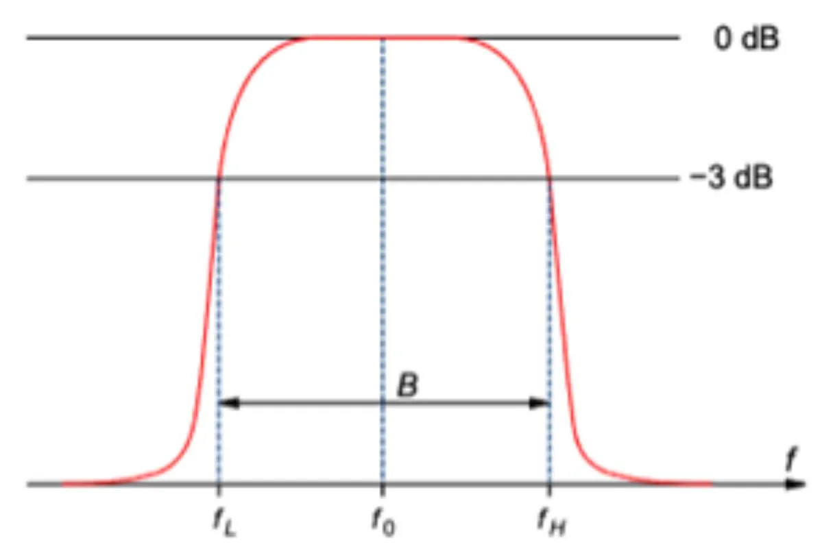
Real filters do not cut off sharply at band edges; the edges are rounded and the attenuation slope is gradual rather than vertical. Key attributes are the center frequency and the upper and lower cutoff frequencies. The cutoff point is commonly defined where signal passage drops by 3 dB, corresponding to half the signal power. The slope beyond 3 dB is often called the skirt, and achieving a steep skirt is important.
While designing the center, upper and lower frequencies independently might be desirable, in practice the upper and lower cutoff frequencies move together to define the center frequency and overall bandwidth. Bandwidth is typically expressed as a percentage of the center frequency. Designing wider passbands is challenging; some 5G bands can be 20% of the center frequency, which places significant stress on filter design.
Filtering should occur as early as possible in the receiver chain to prevent undesired signals from entering the RF path. That implies filtering after the antenna. Massive MIMO arrays that support beam steering use antenna element arrays, and in that case each element would require a filter.
Current antenna element spacing for mmWave is based on millimeter-scale spacing, roughly 5 mm, so filters must accommodate that spacing. — Mike Eddy, VP of Corporate Development, Resonant
Today that spacing makes per-element filtering impractical for mmWave, so filtering commonly occurs after mixing.
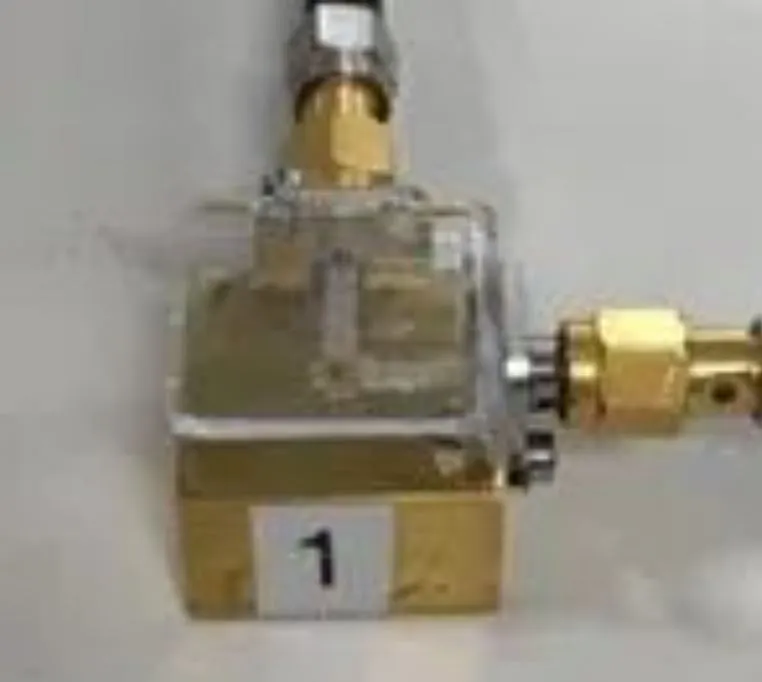
Base stations have more space and can accept larger filters, but phones impose strict size constraints. In the near term, the most feasible small filters may be around 28 GHz, which is a likely mmWave frequency for phones. Higher frequencies are more likely for tower-to-tower links, where space is less constrained.
For base-station use we will rely on ceramic dielectric filters and metal cavity filters, but they cannot meet the space constraints inside mobile devices. — David Vye, Technical Marketing Director, AWR Software, Cadence
In the early days the filtering needs around 28 GHz were more relaxed:
For the first few years we often heard that there would be no mmWave filters in phones because bands were not yet subdivided; antenna filtering was the main approach. — Jeb Flemming, CTO, 3D Glass
Using the antenna as a filter can meet requirements to a point, but eventually antenna elements will require true filters. The question is how to make those mmWave filters.
3. Existing filter technologies
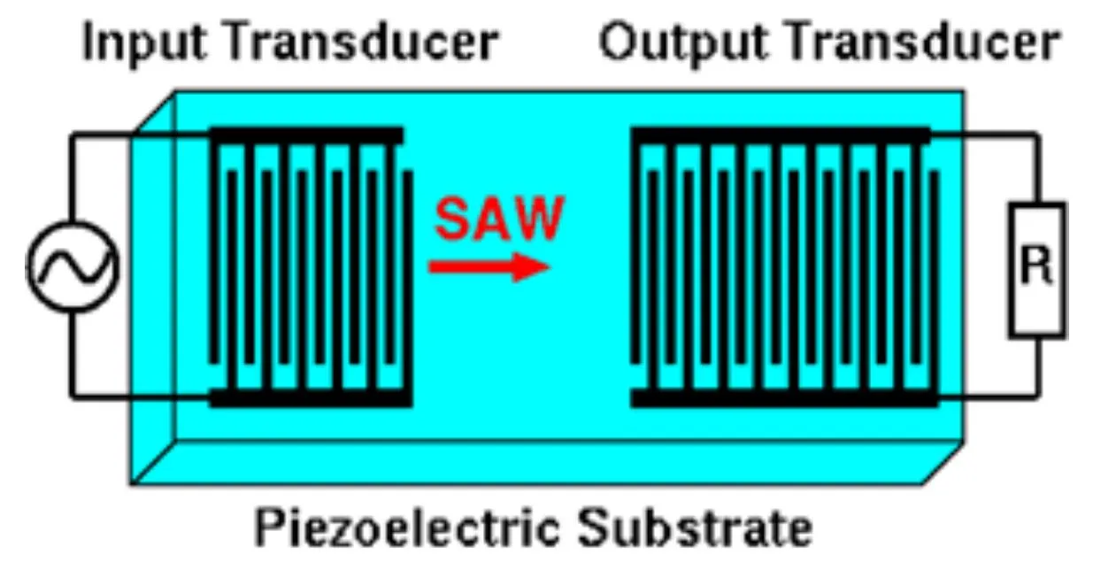
Most filters in phones today use acoustic techniques that involve piezoelectric materials. These materials undergo slight deformation under an electric field and generate an electric field when mechanically deformed. Thus electrical signals convert to mechanical vibrations and vice versa, with those vibrations behaving like acoustic waves in the material.
By building an acoustic resonant structure, an input signal applied to one end of a resonator excites resonances at specific frequencies. The filter removes signals outside the passband; in-band frequency components cause acoustic resonance, which the filter detects and converts back to the electrical domain at the output. Ideally the output consists only of the desired input components with unwanted frequencies removed.
Acoustic filters offer clean passbands, very small size, and favorable cost structure; high-volume production reduces cost further.
At lower frequencies SAW filters dominate. SAW excites waves on the surface of the material and couples them to an output on the same surface.
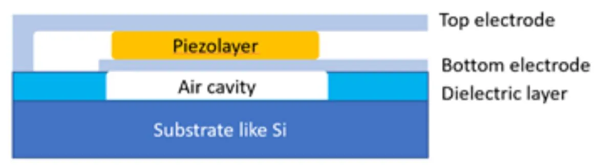
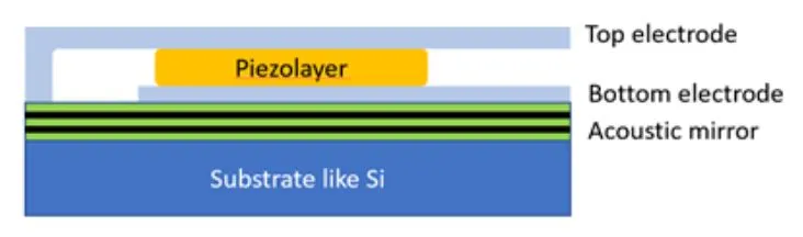
For higher frequencies BAW filters dominate. Unlike SAW, BAW excites resonance through the material thickness, with the output electrode located on the opposite side. Manufacturing is more complex, so BAW filters are generally more expensive than SAW.
BAW filters come in two basic flavors based on how the standing wave is formed. One approach uses a bottom-to-top reflection formed by a freestanding BAW resonator, commonly called FBAR, using an air cavity. The other approach uses alternating layers that act as acoustic mirrors, similar to optical Bragg reflectors, known as the solidly mounted resonator (SMR) BAW filter.
SAW and BAW filters are manufactured with MEMS-like fabrication techniques, but they appear to lose effectiveness at higher frequencies, suggesting the industry may need new filter approaches for the mmWave bands.
4. Options for millimeter-wave filters
Millimeter-wave signals are not new; radar and microwave systems have used them for some time, but those systems often handle only one or two frequencies with large hardware. For 5G, many bands must be filtered more finely and the filters must fit in phones.
SAW and BAW are generally not considered for mmWave, but Resonant has introduced XBAR technology, which claims to extend acoustic techniques to higher frequencies. XBAR redesigns BAW using a different piezoelectric material, lithium niobate, and places both electrodes on the top surface in a configuration that resembles SAW. A key difference is that with XBAR the metal electrodes do not undergo the physical motion associated with SAW resonators:
With SAW, the metal fingers undergo physical motion, which can lead to metal migration and reliability issues. — Mike Eddy, VP of Corporate Development, Resonant
Device models indicate XBAR can provide the power, bandwidth, and handling needed for 5G—especially in the 3 to 5 GHz range. Work is underway on 5 to 7.1 GHz WiFi and then 7 to 9 GHz ultrawideband. The question is whether the model can extend to true mmWave; the company believes it can. — Mike Eddy
XBAR represents a new acoustic approach in this frequency area. Other known mmWave filter technologies include waveguide and cavity filters, which use electromagnetic resonances rather than acoustic ones and offer a wide range of structural choices typically used in microwave applications.
The resonator sizes are frequency-dependent, with dimensions or spacing often around a quarter wavelength. Higher frequency means shorter wavelength and smaller resonator, but for 5G frequencies resonators still remain too large to fit into phones.
There is a dielectric waveguide cavity whose height and width determine which energy can propagate. Below that cutoff frequency energy will not propagate, and above it modulation issues appear. — David Vye, AWR Software, Cadence
Using resonators, typically implemented as posts, helps reduce unwanted modes:
Waveguide cavity filters include posts that function similarly to ceramic filters, stopping or passing energy at specific frequencies depending on post size. The physical spacing between resonators affects bandwidth, and the number of resonators affects attenuation: more resonators yield steeper skirts but increase filter length and material cost. — David Vye, AWR Software, Cadence
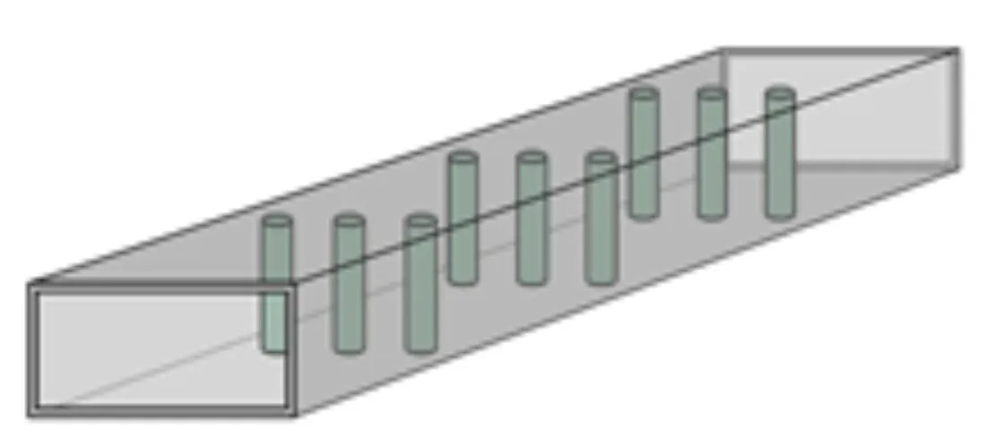
That approach is suitable for base stations because of their available volume, but the filter size remains too large for phones.
Microstrip filters are another option up to about 30 GHz, creating microstrip lines on a PCB to support electromagnetic resonance. However, manufacturing variability and PCB material quality are concerns.
PCB thickness variation, dielectric constant variation, printed trace-width variation, and temperature will alter passband frequencies. — Mike Eddy, Resonant
Material selection also constrains performance. High-Q resonant ceramic materials are limited and often more expensive. Multilayer ceramic capacitors (MLCCs) have been a reasonable material choice but begin to fail around 25 GHz. — Jeb Flemming, CTO, 3D Glass
5. Integrated substrate waveguides
Short mmWave wavelengths make on-substrate waveguides feasible in silicon or other materials:
This is almost like MEMS because channels are created by etching and then metallizing on a silicon wafer. — David Vye, AWR Software, Cadence
3D Glass creates waveguides in glass rather than silicon using photolithography to selectively crystallize amorphous glass under UV exposure. The crystallized glass behaves like ceramic and is easier to etch to form through features.
Ceramic etches about 60 times faster in acid than glass, so cavities can be produced with timed etches because the ceramic layer contains glass inclusions. — Jeb Flemming, CTO, 3D Glass
This approach enables structures such as inductors and cavities with resonators for mmWave filtering:
If metal traces are used as resonators and almost all glass is etched away so resonators are mostly suspended in air, then the limiting factor becomes materials. Removing material and suspending resonators in air can extend operation to 40 to 50 GHz with demonstrated 10% to 15% bandwidth, which is fairly wide. — Jeb Flemming, CTO, 3D Glass
Air-filled cavities can extend to even higher frequencies:
We are doing extensive customer development in the 70 to 150 GHz range, which some call 5G and others call 6G. — Jeb Flemming, CTO, 3D Glass
Past filter designs relied on many manufacturing iterations to optimize performance because variables were numerous and tolerances tight. Today we can use EM simulation tools to optimize structures before fabrication, which helps address critical details:
Packaging and how the filter connects to the rest of the circuit are important. Designers have moved away from purely experiential methods and now rely on EM simulation for design. — David Vye, AWR Software, Cadence
Cadence has worked with 3D Glass using AWR Microwave Office for design and simulation and is familiar with their approach:
Within a very low-loss structure there are metal resonators suspended on small glass pedestals, producing very small filters—although not as small as acoustic filters. — David Vye, AWR Software, Cadence
Conclusion
Glass-based processes have attractive economic potential. Given volume requirements, panels may be used instead of wafers. A 9 x 9 inch panel can accommodate many filters. Although current work often uses 6-inch and 8-inch wafers and some customers are moving toward 12-inch wafers, there is a clear path to cost reduction.
Although several promising possibilities exist, they are not yet ready for full commercial production, and no definitive winner has emerged in filter technology. Millimeter-wave in 5G phones is not fully realized, so more time is required. The industry challenge is to develop a reliable plan and roadmap rather than rely on promising but unproven ideas.


