ALLPCB


Overview
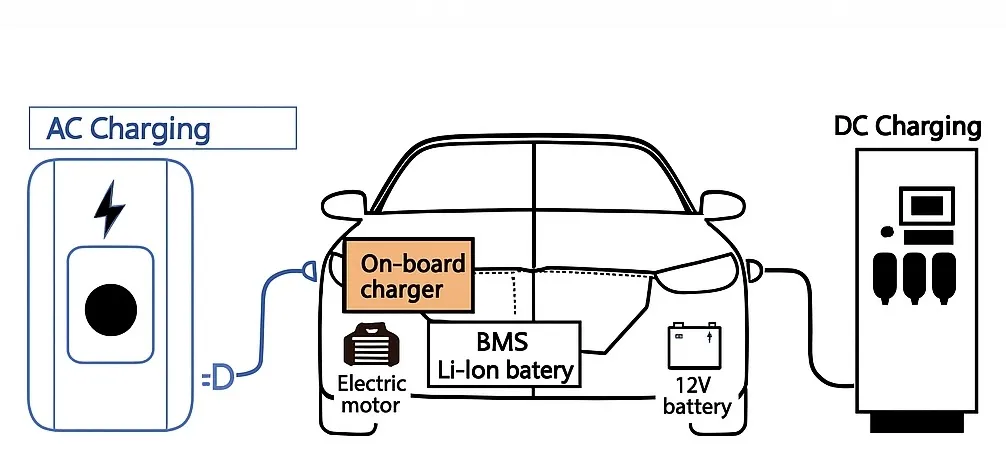
An on-board charger (OBC) converts AC from an AC charging station into the DC required by the vehicle traction battery. Battery-electric vehicles that use AC charging stations require an on-board charger to charge the traction battery.

Understanding the on-board charger
In simple terms, the on-board charger (OBC) is a component installed in an electric vehicle that converts AC power from a charging station into high-voltage DC to charge the vehicle high-voltage traction battery.
By structure, OBCs are classified as unidirectional, bidirectional, or integrated types.
Unidirectional OBCs can only charge the traction battery. Bidirectional OBCs can invert battery DC to provide household 220 V AC, allowing the vehicle to serve as an emergency power source during outages.
The OBC plays a critical role in electric vehicles and performs multiple functions, most importantly communicating with the battery management system (BMS) and the vehicle monitoring system.
It exchanges information with the BMS over a high-speed CAN network so it can dynamically output current and voltage parameters suited to the battery state and select an optimal charging profile. During charging, the BMS mainly monitors pack voltage, current, temperature, and connection status for battery control and protection.
Over the vehicle CAN network, the OBC reports its operating state, parameters, and fault alarms, and accepts start/stop charging commands from the vehicle control system.
The OBC also provides comprehensive safety protections, for example AC input overvoltage protection, AC input undervoltage alarm, AC input overcurrent protection, DC output overcurrent protection, DC short-circuit protection, soft-start to prevent inrush current, and flame-retardant measures. These protections prevent overheating, overcharging, and short circuits to ensure safe and stable battery operation.
Architecture and modules
An on-board OBC consists of the AC input port, power stage, control unit, low-voltage auxiliary unit, and DC output port.
The AC input port receives AC from the grid and typically uses a 7-pin Type 2 connector. Standard input is single-phase 220 V at mains frequency; if higher power is needed, two spare pins can be used to accept 380 V input.
The power stage transfers charging energy and includes EMI suppression, rectification, power factor correction (PFC), filtering, full-bridge conversion, and DC output modules. Coordinated by the control unit, the mains AC is converted into DC at voltages suitable for the traction battery system.
The control unit is the core of the OBC. It controls switching devices in the power stage to accomplish the conversion via closed-loop control and provides protection. Key functions include primary-side detection and protection, overcurrent detection and protection, overvoltage/undervoltage monitoring and protection, and a DSP main controller.
The low-voltage auxiliary unit powers control electronics and provides system interfacing. It typically includes CAN communication, auxiliary power supply, and human-machine interface modules.
The DC output port supplies the battery and typically includes two pins for low-voltage auxiliary power, two pins for high-voltage charging positive and negative, chassis ground, CANH and CANL communication lines (and optional CAN shielding), and a charge request signal line.
Key OBC specifications include input voltage, operating efficiency, power factor, harmonics, output ripple, output voltage, and output current.
Standard QC/T 895-2011 specifies recommended values for input voltage, current, and output voltage, among other parameters.
Power levels, efficiency, and packaging
EV charging power differs between the Chinese market and overseas. Common OBC power ratings are 3.3 kW, 6.6 kW, 11 kW, and 22 kW. An 11 kW OBC means charging a 66 kWh traction battery from empty to full would take about 6 hours.
Conversion efficiency is a major design objective and is closely related to the unit thermal management approach.
Volume, weight, and power density are tightly constrained in automotive applications, driving compact, high-density designs. Current trends integrate OBC and DC/DC into two-in-one units, or OBC+DC/DC+PDU as three-in-one systems, increasing power density and reducing size.
Cooling methods include active air cooling and liquid cooling. Liquid cooling becomes mainstream once power exceeds about 11 kW.
Cost pressures are significant across component suppliers. Competition among smaller three-electric suppliers is intense, and these suppliers typically operate with gross margins in the mid-teens to around 20%.
Typical OBC architecture
Most OBCs use a two-stage architecture. The front-end PFC corrects the power factor and typically outputs around 400 V DC. The rear-stage DC/DC draws from the PFC bus to provide isolation and voltage regulation. Since the DC/DC output supplies the battery, it commonly provides 200–500 V high-voltage DC, so the rear stage must use a high-efficiency, wide-range isolated DC/DC topology.
The OBC hardware comprises the power stage and the control stage. The power stage includes the front-end AC-DC and the rear-stage DC-DC circuits. The control stage consists of sensing and parameter feedback circuits that adjust setpoints via PWM to control switching timing in the high-voltage circuit, achieving target output current and voltage and performing fault monitoring.
Regardless of per-stage circuit design, the goals are higher switching frequency, high power factor, and high efficiency.
Front-end AC-DC PFC topologies
Front-end AC-DC circuits commonly use basic or improved boost APFC converters, including basic boost APFC, bridgeless boost APFC, interleaved boost APFC, and bridgeless interleaved boost APFC variants.
Conventional bridged boost PFC: When Q1 is on, the positive half-cycle conduction path is D1, L1, Q1, D4; the negative half-cycle path is D2, L1, Q1, D3. When Q1 is off, the positive half-cycle path is D1, L1, D5, Rd, D4; the negative half-cycle path is D2, L1, D5, Rd, D3.
Interleaved parallel boost PFC: This topology parallels two identical boost PFC converters to reduce per-phase inductance. By controlling the two inductor currents to be 180° out of phase, input and output current ripple is reduced, allowing a smaller EMI filter. The control and power flow are similar to the conventional bridged design, with added switching devices.
Bridgeless boost PFC: The rectifier bridge from a conventional PFC is removed to reduce the number of switching devices. In the positive half-cycle, when Q1 is off the power path is L1, D1, Rd, Q2, L2; when Q1 is on the path is L1, Q1, Q2, L2. In the negative half-cycle, when Q2 is off the path is L2, D2, Rd, Q1, L1; when Q2 is on the path is L2, Q2, Q1, L1. Compared with the bridged PFC, fewer active devices appear in the conduction path, which helps improve system efficiency. For devices with built-in anti-parallel diodes, Q1 and Q2 can share a single drive signal.
Dual bridgeless boost PFC: Compared with the single bridgeless PFC, the dual bridgeless design improves EMI performance. In the positive half-cycle, when Q1 is off the power path is L1, D1, Rd, D4; when Q1 is on the path is L1, Q1, D4. In the negative half-cycle, when Q2 is off the path is L2, D2, Rd, D3; when Q2 is on the path is L2, Q2, D3. The control method is similar to the basic bridgeless PFC, and the additional diodes significantly reduce interference but increase system cost.
Totem-pole boost PFC: This topology can address EMI issues in bridgeless PFCs. In the positive half-cycle, when Q1 is off and Q2 is on the power path is L, Q2, D2; when Q2 is off and Q1 is on the path is L, Q1, Rd, D2. In the negative half-cycle, when Q1 is off and Q2 is on the path is D1, Rd, Q2, L; when Q1 is on and Q2 is off the path is D1, Q1, L. This topology is control-complex: the upper device drives require floating drive circuitry, raising design difficulty and cost. Also, Q1 and Q2 can exhibit reverse recovery issues that increase losses.
Isolated DC-DC topologies
DC-DC converter topologies include buck, boost, buck-boost, phase-shifted full-bridge, and resonant converters. For OBC applications, isolated DC-DC converters are preferable regarding power levels and electrical safety. Common isolated topologies are phase-shifted full-bridge, dual active bridge, and LLC resonant converters.
Phase-shifted full-bridge: This can achieve a wide range of output voltages with near-zero-voltage switching. The leading-arm devices Q1 and Q3 have a 180° phase difference in drive signals; the lagging-arm devices Q2 and Q4 are phase-shifted relative to Q1 and Q3. By varying phase angles between drive signals, transformer leakage inductance and device junction capacitance can resonate to enable soft switching. Drawbacks include duty-cycle loss on the secondary due to transformer leakage inductance and diode voltage spikes on the secondary. The required LC output filter increases circuit volume and introduces additional losses.
Dual active bridge (DAB): By phase-shifting primary and secondary bridges, the DAB controls energy flow direction and magnitude and can achieve zero-voltage turn-on. It is often used in high-power bidirectional DC-DC converters. This topology offers high power density and efficiency and supports bidirectional power transfer, making it suitable for electric vehicles and aerospace applications.
LLC resonant converter: The LLC enables soft switching and offers a large regulation range within a relatively narrow frequency band. It has favorable light-load behavior. Transformer leakage inductance can be reused as magnetizing inductance, reducing magnetic component size and improving power density, while providing high efficiency and low EMI.
Development trends
Mainstream vehicle models are upgrading OBC output power from 3.3 kW to 6.6 kW. Future OBCs will trend toward higher power levels, smaller size, bidirectional capability, and higher integration.
A 6.6 kW OBC has become mainstream in the Chinese market and is moving toward 11 kW and even 22 kW. Manufacturers are developing two-in-one, three-in-one, and even multi-in-one integrated solutions. Common two-in-one examples include 6.6 kW OBC + 1.5 kW DC/DC; a three-in-one example is 6.6 kW OBC + 2 kW DC/DC + PDU.
Some OBC designs adopt SiC MOSFETs. Example system block diagrams for OBCs using SiC devices include: