ALLPCB


Introduction
Relays are widely used electrical products. Performing reliability assessment and failure prediction for relays in the field can prevent system faults caused by false units and reduce economic loss from discarding good parts. As common components in automatic control circuits, relays control the opening and closing of switch circuits. They can be actuated by electrical signals or by magnetic, acoustic, optical, or thermal means, and are used across industry, power, aviation, and automotive electrical control systems. In vehicle performance testing, relay failures often cause circuits to fail to open or close properly, resulting in abnormal electrical function. This article reviews automotive relay selection and analyzes common failure models using failure case studies to help mitigate risks and improve vehicle electrical reliability.
Relay Construction and Operating Principle
Construction
A typical relay consists of a core, coil, armature, return spring, and contacts.
Operating Principle
When a certain voltage or current is applied across the coil terminals of an electromagnetic relay, the magnetic flux produced by the coil passes through the core, yoke, armature, and the air gap to form a magnetic circuit. Under the magnetic force, the armature is attracted to the pole face of the core, causing the normally-closed contact to open and the normally-open contact to close. When the coil is de-energized, mechanical restoring force returns the armature to its initial position, so the normally-open contact opens and the normally-closed contact closes.
Classification and Selection
3.1 Relay Classification
1) By mounting type: PCB relays and plug-in relays. Plug-in relays include ISO types (Micro ISO, Mini ISO, Power Mini ISO) and 280 types (Ultra 280, Micro 280, Mini 280).
2) By contact structure: single-pole single-throw (SPST) and single-pole double-throw (SPDT), as shown below.
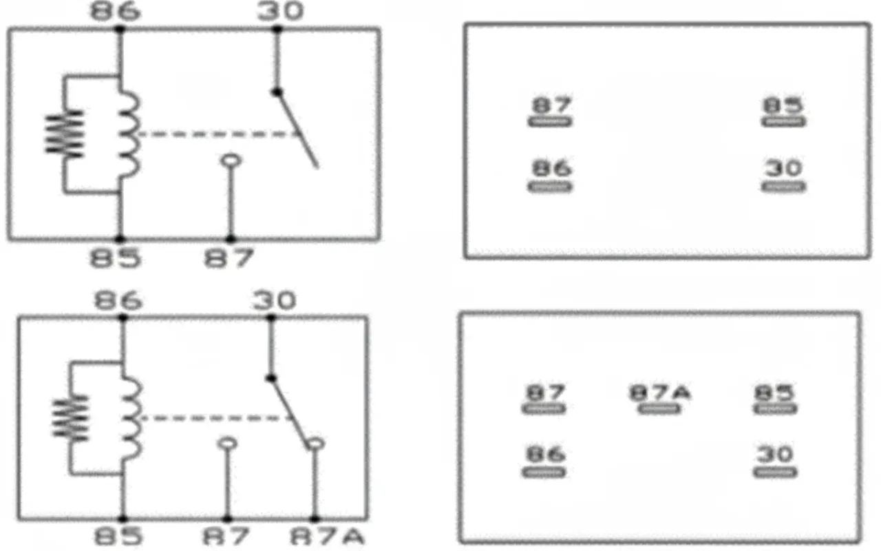
SPST and SPDT relays
3.2 Relay Selection
1) Electrical life: Select relays based on load type. Conventional loads typically require relays rated for more than 100,000 cycles. Loads with frequent vacuum pump starts should use relays rated for 800,000 cycles of electrical durability.
2) Coil voltage: Coil voltages are 12 VDC and 24 VDC; automotive relays typically use 12 VDC.
3) Contact form: Choose according to load and system design. Except for wiper relays and motor forward/reverse loads, which require changeover contacts, most applications use a single normally-open contact.
4) Package type: Relay packages include plastic-sealed (S) and dust-cover types. Plastic-sealed versions offer better waterproofing and suit wet environments. Dust-cover versions provide better heat dissipation.
5) Contact material: Contacts must resist welding, arc erosion, and oxidation. Depending on load current and life requirements, contact alloys may include trace elements such as indium.
6) Switching current ratings: Loads are classified as resistive (defroster, cigarette lighter, conventional loads), inductive (blowers, oil pumps, motors), and lamp loads. Choose relay make and break current ratings greater than the load’s starting peak current and operating current. Low-current loads below 0.3 A require special signal relays.
7) Coil power: Coil power consumption determines the drive capability required from the control circuit. The control pin current capability should exceed the coil power demand.
Common Failure Modes
4.1 Stuck-Closed (Contact Welding)
Contact welding is a common failure mode. Causes include excessive current, switching frequency exceeding the relay rating, and abnormal vibration at the contact area, all of which can lead to contact adhesion.
4.2 Coil Open or Failure to Pull In
Failure to close is often due to coil terminal faults. Common causes include coil wire breakage from overvoltage or from ultrasonic cleaning, and insufficient coil pull-in force due to incorrect supply voltage.
4.3 Closed But Not Conducting
This failure occurs when the closed contact does not conduct, often due to contact contamination, structural defects (incorrect contact gap, broken spring), or loose riveted connections.
Failure Case Studies
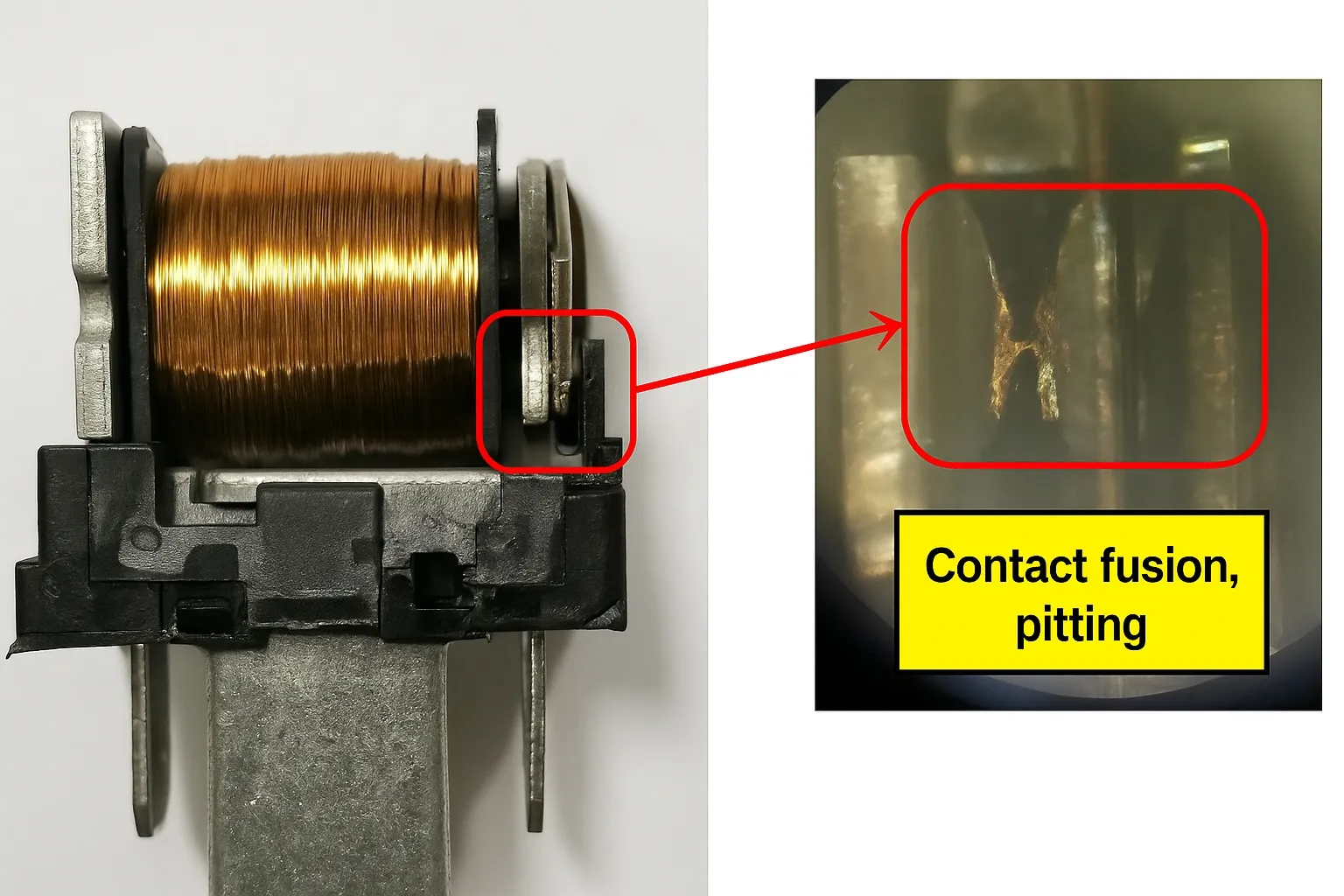
5.1 Contact Welding Case
During a high-temperature durability test, a test vehicle’s fan continued running for an extended period after the engine was shut off. Diagnostic checks showed no fault codes across the vehicle.
5.1.1 Failure analysis:
Investigation found voltage present at the high-speed fan relay output. Disassembly revealed that the moving and stationary contacts had melted due to high temperature, causing contact welding and relay failure.
5.2 Coil Break Failure
During a durability test while using the air conditioning, one test vehicle had no blower airflow.
5.2.1 Failure analysis:
Applying a simulated control signal to the blower relay coil produced no voltage at the relay output, indicating suspected coil terminal failure. Disassembly showed the enamel-coated coil wire had been mechanically crushed and broken, creating an open circuit in the coil and preventing relay pull-in.
5.3 Closed But Not Conducting Case
During a durability road test, a vehicle experienced intermittent no-start or stalling. Investigation found the fuel pump relay in the electrical box had no voltage output.
5.3.1 Failure analysis:
Disassembly of the faulty relay showed contamination on the moving contact. Energy-dispersive analysis identified sodium (Na) and potassium (K) as major constituents of the contamination. Prolonged accumulation of these contaminants on the moving contact prevented reliable conduction, causing the fuel pump relay to fail.
Conclusion
By correlating relay issues observed in vehicles with symptom analysis and root-cause investigation, the failure mechanisms were identified and addressed. Because relays directly affect vehicle electrical functions, understanding relay construction, operating principles, and failure modes helps guide relay selection and improve overall vehicle electrical reliability.