ALLPCB


Lead-free Hot Air Solder Leveling (HASL) serves as a widely adopted surface finish for printed circuit boards in electronics manufacturing. This process applies a solderable coating to exposed copper pads and traces, ensuring reliable connections during assembly. Engineers focus on coating thickness because it directly influences wetting behavior, intermetallic compound formation, and long-term joint reliability. Proper control of lead-free HASL thickness supports compliance with environmental regulations while maintaining electrical and mechanical performance across demanding applications.
Why Lead-Free HASL Thickness Matters in PCB Manufacturing
Lead-free HASL replaces traditional tin-lead alloys with compositions such as tin-copper or tin-silver-copper to meet RoHS requirements. The resulting coating tends to be thinner and more uniform than its leaded counterpart due to differences in surface tension and flow characteristics during the hot air leveling step. Thickness consistency affects solderability, particularly on fine-pitch components where uneven coverage can lead to defects. Industry professionals measure and specify this parameter to balance cost, process yield, and end-product durability. Variations in coating thickness can alter the volume of solder available for joint formation, impacting both initial assembly success and resistance to thermal cycling stresses.
Technical Principles of Coating Thickness and Solder Joint Strength
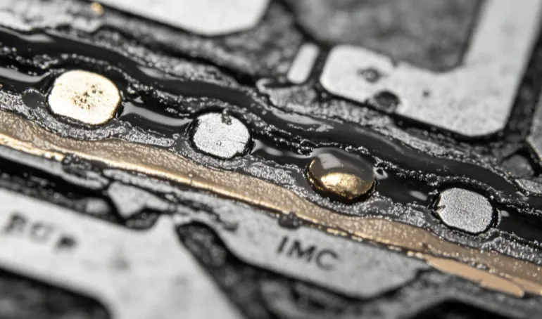
The thickness of a lead-free HASL coating determines how effectively molten solder wets the copper surface during reflow. Adequate thickness promotes the formation of a controlled intermetallic layer that anchors the joint without excessive brittleness. Insufficient coverage may expose copper, reducing solderability and increasing the risk of weak or open joints. Conversely, excessive thickness can create bridging risks on closely spaced pads or contribute to uneven surfaces that affect component placement accuracy. Surface tension forces during the HASL process naturally limit buildup, often resulting in coatings that range from several micrometers on smaller features to thicker deposits on larger areas. Engineers evaluate these effects through process controls that account for pad geometry, board design rules, and thermal profiles.
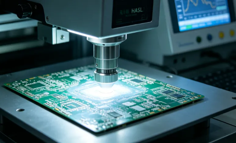
X-ray fluorescence provides a non-destructive method for verifying coating thickness across production panels. This technique measures elemental composition and layer depth with high repeatability, allowing manufacturers to confirm uniformity before boards proceed to assembly. Consistent thickness readings correlate with improved solder joint strength by ensuring predictable intermetallic growth rates during soldering operations. Standards such as those from IPC guide acceptable ranges and inspection criteria for surface finishes in rigid printed boards.
Best Practices for Controlling and Measuring Lead-Free HASL Thickness
Process optimization begins with precise control of solder pot temperature, dwell time, and hot air knife parameters. These variables influence how much alloy remains on the pads after leveling. Regular calibration of equipment helps maintain target thickness profiles suited to specific board layouts and component requirements. Design teams incorporate appropriate pad sizes and thermal relief patterns to minimize thickness variations between features.
Measurement protocols typically employ X-ray fluorescence for production monitoring because it delivers rapid, accurate data without damaging the board. Sampling plans often focus on critical areas such as fine-pitch pads and via sites to detect deviations early. When measurements fall outside established tolerances, adjustments to the HASL line or secondary inspection steps can restore compliance. Documentation of thickness data supports traceability and aids in root-cause analysis during quality reviews.
Collaboration between design and manufacturing teams ensures that specified thickness targets align with assembly processes. This includes reviewing solder paste volume calculations and reflow profiles to complement the HASL coating characteristics. Implementing statistical process control on thickness measurements reduces variability and enhances overall solder joint reliability.
Practical Considerations for Engineers Working with Lead-Free HASL
Engineers assess lead-free HASL thickness in the context of the full assembly environment, including component lead finishes and expected operating conditions. Thinner coatings common in lead-free processes require careful attention to flux selection and reflow atmosphere to achieve optimal wetting. Joint strength testing, such as shear or pull tests, helps validate that thickness choices deliver the required mechanical performance under thermal and mechanical loads.
Troubleshooting thickness-related issues often involves reviewing X-ray fluorescence data alongside visual and microscopic inspections. Uneven readings may point to issues with board warpage, solder alloy composition, or leveling equipment settings. Addressing these factors early prevents downstream defects that compromise solder joint integrity.
Conclusion
Lead-free HASL thickness plays a central role in achieving reliable solder joints by influencing wetting, intermetallic formation, and overall joint robustness. Through disciplined process control and precise measurement techniques such as X-ray fluorescence, manufacturers can deliver consistent coatings that meet performance expectations. Engineers who integrate thickness considerations into design and quality workflows contribute to higher yields and longer product life cycles. Adherence to established industry practices ensures these benefits without unnecessary complexity.
FAQs
Q1: What is the typical thickness range for lead-free HASL coatings?
A1: Lead-free HASL coatings generally measure thinner than traditional tin-lead versions, with typical values falling in ranges that support good solderability while minimizing excess material. Measurement using X-ray fluorescence confirms these values during production to maintain consistency.
Q2: How does lead-free HASL thickness affect solder joint strength?
A2: Appropriate coating thickness promotes uniform wetting and controlled intermetallic growth, directly contributing to stronger, more reliable solder joints. Deviations can weaken joints by limiting available solder volume or creating stress concentrations during thermal cycling.
Q3: Why use X-ray fluorescence for lead-free HASL thickness measurement?
A3: X-ray fluorescence offers non-destructive, repeatable assessment of coating thickness and composition across multiple board locations. This method supports efficient quality control without altering the surface finish.
Q4: What standards guide lead-free HASL thickness specifications?
A4: Standards from IPC provide frameworks for qualifying and inspecting surface finishes on printed boards, helping ensure thickness parameters align with assembly and reliability requirements.
References
IPC-6012E — Qualification and Performance Specification for Rigid Printed Boards. IPC, 2017
IPC-A-610G — Acceptability of Electronic Assemblies. IPC, 2017
J-STD-002E — Solderability Tests for Component Leads, Terminations, Lugs, Terminals and Wires. IPC, 2017