ALLPCB


Overview
With the introduction of the MTi-8 and MTi-680(G) RTK GNSS/INS products, Xsens added a configuration parameter called the GNSS lever arm. The GNSS lever arm is a fundamental parameter for obtaining reliable centimeter-level position, velocity, and orientation data. This article provides a detailed explanation of the GNSS lever arm and its role in the GNSS/INS sensor fusion process.
What the GNSS lever arm represents
The GNSS lever arm records the relative position between the MTi sensor reference point (the point where inertial measurements are taken) and the GNSS receiver antenna. Providing this offset to the MTi allows the sensor fusion algorithm library to compensate for the dynamic differences between the two measurement locations. The diagram below visualizes these dynamic differences:
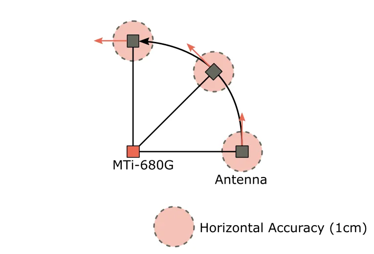
In the illustration, the MTi is mounted near the rotation center of the platform, for example a car, robot, or drone. The GNSS antenna is mounted elsewhere on the same vehicle, at a distance from the MTi that is large relative to the GNSS receiver's measurement precision. When the vehicle rotates, the MTi remains at the same global location and mainly experiences rotation. In contrast, the GNSS antenna experiences both rotation and linear displacement.
Why provide the lever arm to the fusion algorithm
There are two main reasons to supply the lever arm to the MTi sensor fusion library. First, knowing the exact offset allows the fusion algorithm to transform GNSS receiver measurements so they match the dynamics of the inertial measurements. An incorrect lever arm can produce undefined state estimates and degrade fusion performance, causing errors in estimated position, velocity, and orientation. For example, the MTi might interpret GNSS observations as vehicle motion when in fact the vehicle is only rotating about its axis.
Second, the lever arm is subtracted from the position output generated by the MTi so that the reported position refers to the MTi location rather than the GNSS antenna location.
Relation between GNSS accuracy and lever arm importance
In short, as GNSS measurement accuracy increases, the lever arm becomes more important. Consider the earlier visualization: when the GNSS receiver provides centimeter-level accuracy, it can clearly resolve the antenna's path between successive measurements. If the GNSS receiver accuracy is only around 1 meter, three consecutive measurements may not be precise enough to determine the antenna's path. Given limited measurement precision, the antenna motion may not be distinguishable and the lever arm will be ignored by the MTi.
The importance of the lever arm also depends on its length. For example, on a large ship with an MTi-G-710 mounted near the hull center and an antenna on a mast 10 m above the MTi, significant roll and pitch will produce observable linear displacement of the antenna even with lower-accuracy GNSS receivers. In such cases, providing the lever arm to the fusion algorithm can improve MTi performance.
Currently, MTi-8 and MTi-680(G) in the MTi product range support this lever arm setup because their position data are accurate to the centimeter level. The sensor fusion algorithms used for MTi-7, MTi-670, and MTi-G-710 assume the GNSS antenna position is approximately the same as the MTi itself.
How to measure and store the GNSS lever arm
The GNSS lever arm is a parameter the user must measure and save after installing the MTi. It is stored in the MTi memory as an X-Y-Z coordinate vector relative to the MTi sensor coordinate frame origin. Units are meters, but the lever arm should be determined with centimeter-level precision when possible.
Note: The default GNSS lever arm value is [0, 0, 0] (m). By default, the MTi therefore assumes the MTi and its GNSS antenna share the same location.
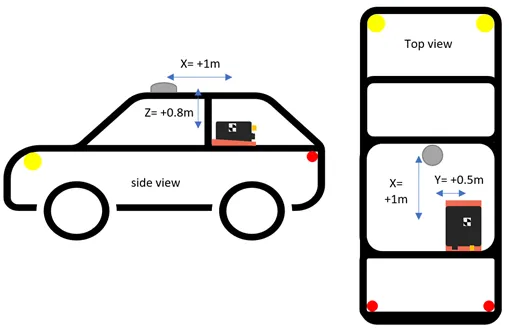
The diagram below shows an example of measuring the GNSS lever arm after installing an MTi and GNSS antenna in a car. The X-Y-Z coordinates should be measured according to the sensor coordinate frame printed on the side label of the MTi. Pay attention to coordinate signs: if the antenna is mounted to the right of the MTi, the Y coordinate should be negative. In this example the final vehicle lever arm vector is [1.00, 0.50, 0.80] (m).
The lever arm can be set and stored using the Device Settings window in MT Manager or via the low-level setGnssLeverArm communication command. If the MTi-8 or MTi-680(G) is not aligned with the tracked object, a sensor alignment matrix (RotSensor) can be applied to compensate for this. Note that the lever arm should still be entered relative to the original sensor coordinate frame printed on the MTi label. The GNSS lever arm is not affected by the RotSensor matrix.
The exact location of the MTi origin can be found in the product datasheet.
Consequences of incorrect lever arm usage
The GNSS lever arm is treated as a static offset, meaning the fusion algorithm assumes the relative distance (relative to the MTi sensor coordinate frame) does not change over time. Providing an incorrect lever arm may degrade the MTi's position, velocity, and orientation output.
Lever arm assumptions can be violated when the MTi and GNSS antenna are mounted on a flexible (nonrigid) vehicle or object. Incorrect usage also frequently occurs during desktop testing: for example, connecting the MTi to a PC while leaving the GNSS antenna near a window to obtain an RTK fix. If the MTi itself moves or rotates, the lever arm assumption is violated.