ALLPCB


Overview
Touchscreen controls are widely used as a convenient and robust interface for interacting with complex equipment designed to automate processes or perform tasks humans cannot do directly. However, touchscreens are unsuitable where hygiene is a priority, such as in food processing or healthcare, or where operators must wear protective gloves.
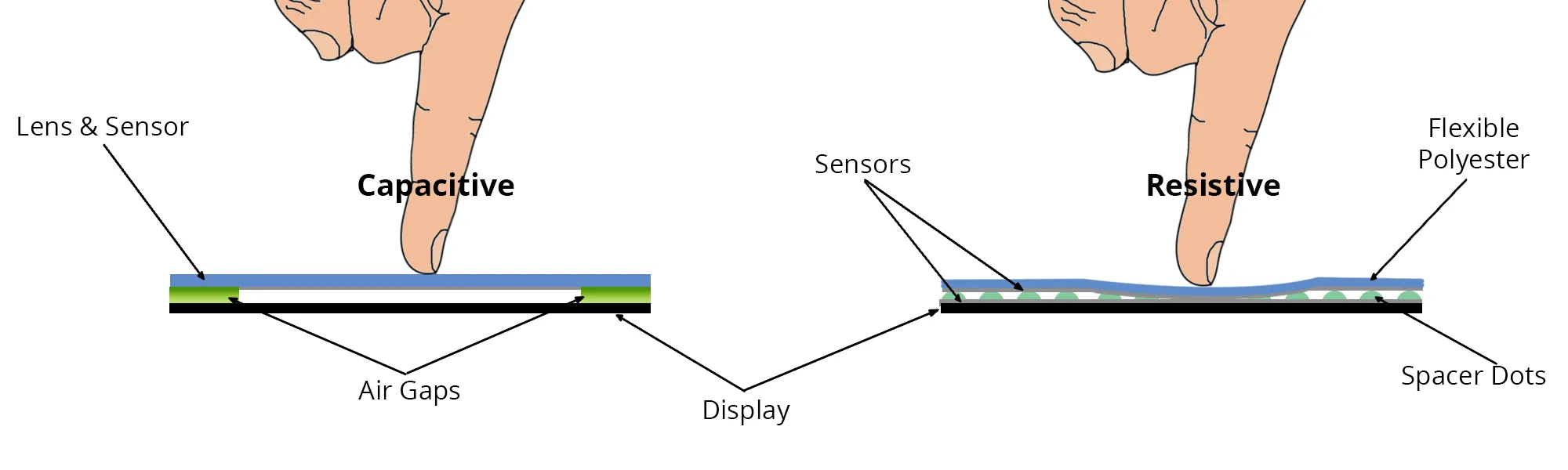
When workers must interact with food production equipment, touchscreen surfaces can spread contamination. Similarly, when configuring medical devices such as dialysis machines, users may need to change gloves after every touchscreen interaction. In industrial scenarios that require thick protective gloves, conventional capacitive touchscreens may not respond reliably or may risk incorrect touches. Requiring users to remove gloves reduces safety and productivity.
3D Gesture Recognition as a Touchless Alternative
3D gesture recognition features such as hand tracking and proximity detection can interpret commands without physical contact with the sensor surface. Controlling a device through natural hand and finger movement in free space helps designers address the limitations of conventional capacitive touchscreens.
Optical gesture recognition achieved by model analysis or time-of-flight measurements can help game controllers detect full-body movement and can be used for short-range 3D gesture detection as a touchscreen substitute. However, implementing optical gesture sensing in a control panel may require holes or openings for light sources and detectors, and might need multiple light sources and/or receivers, increasing cost and complexity.
Electrical near-field (electric-field) sensing is an alternative that uses front-panel embedded electrodes or display-integrated electrodes. It can detect various gestures such as hand approach, swipes or edge taps to move or select next/previous options, and circular gestures to control clockwise or counterclockwise rotation.
Simplifying Electric-Field Sensing
The Microchip MGC3030 gesture controller is an electric-field sensing system-on-chip with onboard processing for 3D gesture recognition and hand-position tracking. It implements Microchip's GestIC technology, applying an AC voltage around 100 kHz to energize electrodes and establish a quasi-electrostatic near field that distorts when a hand or finger enters the sensing region. The compression of equipotential lines reduces the signal level at the sensor array. GestIC algorithms analyze these changes to detect approach behaviors and interpret gestures, using statistical modeling to distinguish deliberate gestures from general hand movement.
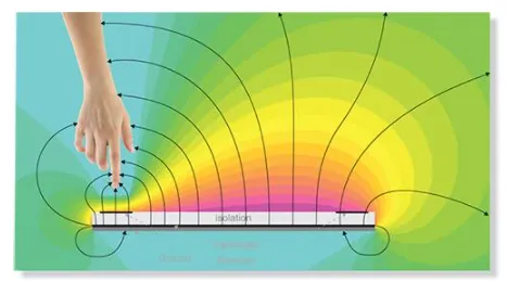
Figure 1: GestIC algorithms identify gestures by analyzing quasi-electrostatic field distortion.
The MGC3030 runs GestIC algorithms on a 32-bit DSP core and uses analog filtering and frequency hopping to minimize interference. The algorithms require less centralized processing than optical gesture recognition and, combined with the MGC3030 power-management modes, including wake-on-approach, provide a cost-effective, low-power solution suitable for battery-powered devices that need continuous sensing.
In addition to common gestures, the GestIC suite supports touch detection such as tap and double-tap. It also supports the "airwheel" circular gesture with adjustable resolution up to 32 counts per revolution, and x-y-z position tracking that enables custom gestures or sensed input.
Sensor Design Guidelines
The design and layout of transmitter and receiver electrodes typically affect gesture recognition range, accuracy, and repeatability. The MGC3030 provides pins for up to five receive electrodes and one transmit electrode. Electrodes can be made from any conductive material, such as woven solid copper mesh, metal mesh, or indium tin oxide (ITO). Transmit and receive electrodes are separated by a nonconductive isolation layer made from a printed circuit board substrate, glass, polycarbonate, or similar material. A nonconductive cover layer can also be added.
The IC transmitter output amplitude is 2.85 V, suitable for sensors up to approximately 140 mm x 140 mm. For larger sensors up to about 200 mm x 200 mm, a level shifter can increase the output using a 5 V to 18 V supply provided by the system power rails or a dedicated boost converter.
Regarding electrode shape, sensors are typically square or round, but rectangular or elliptical shapes with aspect ratios up to 1:3 are acceptable. If a symmetric detection range is required, the sensor shape should be symmetric about the X and Y axes.
Receive electrodes should be arranged around the sensor, preferably with equal or similar lengths. Electrode width is generally 5–7% of its length. Increasing width raises the capacitance to a nearby hand and reduces the gesture detection range, which can be beneficial for weakly grounded systems such as battery-powered devices.
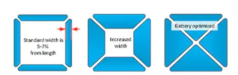
Figure 2: Increasing electrode width increases capacitance but reduces detection range.
Four electrodes are commonly used to recognize gestures, as shown in Figure 2. The MGC3030 fifth electrode input can implement a central touch area, while an outer ring electrode can be used for proximity detection or as an additional touch button outside the gesture sensing area.
The transmit electrode generates the electric field and is placed below the receive electrodes in the sensor stack. This arrangement can shield the back of the sensor and the electrical connections from potential interference. For optimal shielding, the transmit electrode should overlap the receive electrodes.
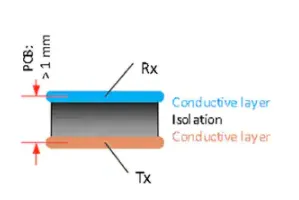
Figure 3: Cross-section of a dual-layer sensor stack.
To minimize external noise, the transmit electrode should cover the full sensor area. This is important when adding gesture detection to a TFT display. Designers may arrange the sensor as a ring around the display; using transparent electrodes such as thin ITO on the display can ensure better performance.
The MGC3030 gesture controller should be placed as close to the electrodes as possible, even if that places it away from the direction users are most likely to approach. A suitable solution is mounting the IC on the rear side of the sensor PCB, either within the sensor area or near the outer edge.
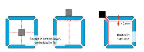
Figure 4: Chip placement and electrode connections.
Wires connecting receive electrodes to IC input pins are sensitive to disturbances from hands and the environment, so they should be as short as possible and kept away from external interference sources. For stable and consistent operation, use mechanically secure conductors for flexible connections, such as PCB traces and/or board-to-board connectors, rather than movable cables.
The isolation layer between the top receive electrodes and the underlying transmit electrode also affects sensor performance through its dielectric properties. If a PCB is used as the insulator, standard FR4 (relative permittivity εr = 5) should be at least 1.0 mm thick; increasing thickness to 1.5 mm–2.0 mm significantly improves performance. Glass insulators (εr = 6) should be at least 1.2 mm thick, while plastics (typical εr ≈ 3.0) can be as thin as 0.6 mm.
In battery-powered systems, a ground plane is required. Adding an additional ground layer can improve stability and minimize sensitivity to interference from the sensor rear.
If a ground layer is used, implement it as a third layer beneath the transmit electrode. In that case, the maximum allowable capacitance between the transmit electrode and ground is limited by the IC's transmitter drive capability and must not exceed 1 nF. Various techniques can reduce this capacitance if necessary, including replacing the insulator with a lower-permittivity material, increasing the distance between transmit electrode and ground, using a mesh electrode instead of a solid electrode, or inserting an external voltage follower as a driver between the IC output and the transmit electrode.
Detailed Design Assistance
Although GestIC technology facilitates quick implementation of gesture recognition, proper sensor design critically affects operating range and sensor stability. Table 1 summarizes common problems caused by poor sensor design, likely causes, and possible remedies.
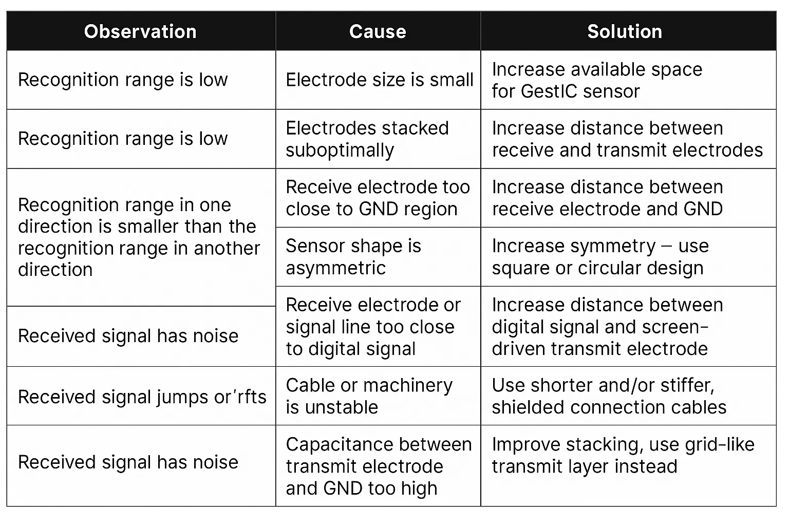
Table 1: Electric-field sensor troubleshooting guide.
Conclusion
As an alternative to touch-based user interfaces, electric-field sensing provides a practical approach to implement 3D gesture recognition. Microchip's GestIC technology simplifies implementation and can recognize gestures suitable for controlling industrial and medical devices. Touch sensors can still be implemented where needed. Investing time to follow basic sensor design guidelines helps optimize performance and reliability and shortens time to market.