 ALLPCB


Introduction
Time delay relays offer hobbyists a fun way to add automation and timing control to their electronic projects. These versatile components allow circuits to perform actions after a set delay, making them ideal for applications like automatic lighting or motor sequencing. Whether you are building on a breadboard or designing a custom PCB, experimenting with time delay relay projects can enhance your understanding of timing circuits. This article explores key types, such as delay on make relays and delay on break relays, along with practical timer relay applications. You will find step-by-step project ideas tailored for electronic hobbyists, including adjustable time relay circuits. Get ready to turn simple ideas into working prototypes that demonstrate real-world utility.
What Are Time Delay Relays and Why They Matter for Hobbyists
A time delay relay is an electromechanical or solid-state device that introduces a programmable delay between the activation of its control signal and the switching of its output contacts. Common types include the delay on make relay, which waits before closing the circuit after power-up, and the delay on break relay, which holds the circuit closed for a set time after power removal. These relays rely on internal timing mechanisms like RC networks or digital counters to achieve precise delays ranging from milliseconds to hours. For hobbyists, they matter because they enable cost-effective automation without complex microcontrollers. In timer relay applications, such as home automation or robotics, they provide reliable sequencing that prevents issues like inrush currents damaging components. Understanding these relays empowers you to create robust projects that mimic industrial controls on a small scale.
Hobbyists appreciate time delay relays for their simplicity and adaptability in breadboard experiments or PCB layouts. They integrate easily with basic components like resistors, capacitors, and transistors, allowing custom delay adjustments. Safety improves in projects involving motors or lights, as delays avoid sudden surges. Moreover, these relays teach fundamental principles of electronics, bridging analog and digital worlds. As you experiment, you will see how small changes in component values dramatically alter timing behavior.
Technical Principles Behind Time Delay Relays
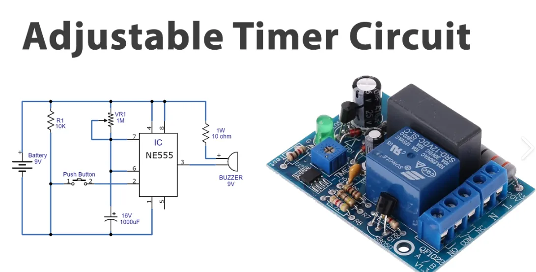
Time delay relays operate on principles of charging or discharging capacitors in conjunction with resistors or integrated circuits to create predictable time intervals. In a basic adjustable time relay circuit, a resistor-capacitor (RC) network determines the delay by the formula tau = R * C, where tau is the time constant. When voltage applies, the capacitor charges gradually until it reaches a threshold that triggers the relay coil, as seen in delay on make configurations. Conversely, delay on break relays discharge the capacitor upon signal removal, maintaining the relay energized until fully discharged. Solid-state versions use CMOS timers for greater accuracy and lower power consumption compared to mechanical ones.
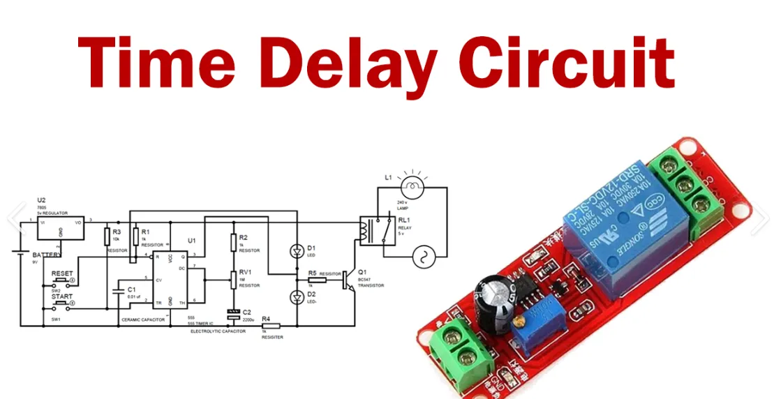
Many commercial time delay relays adhere to standards like IEC 61812-1, which specifies requirements for timing accuracy and environmental durability in industrial settings. Hobbyists can replicate these using the ubiquitous 555 timer IC in astable or monostable modes for versatile operation. Voltage levels typically range from 5V to 24V DC, with relay contacts rated for loads up to several amps. Temperature variations affect capacitor performance, so select components with stable dielectrics like polyester or tantalum. Oscilloscope traces reveal the exponential curves central to these mechanisms, helping debug timing issues.
Power supply stability is crucial, as fluctuations can skew delays. Threshold comparators inside the timer detect when the capacitor voltage crosses set points, activating transistors to energize the relay. Multi-function relays combine modes like on-delay, off-delay, and interval timing in one package for advanced timer relay applications.
Hands-On Time Delay Relay Projects for Hobbyists
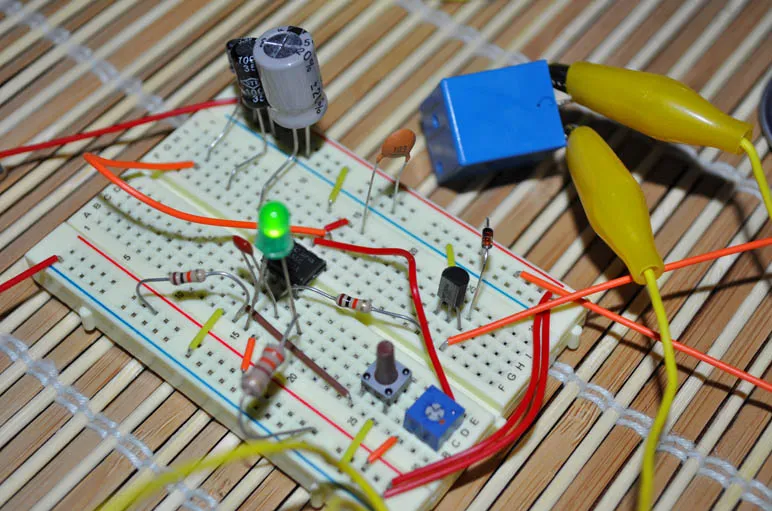
Start with a classic delay on make relay project: an automatic porch light timer. Wire a 555 timer in monostable mode with a potentiometer for adjustable delay from 1 to 60 seconds. Connect the relay output to control a lamp; upon pressing a button, the light turns on after the set delay, simulating dusk activation. Prototype on a breadboard, then transfer to a perfboard for permanence. This time delay relay project teaches component selection and demonstrates practical energy savings.
For a delay on break relay application, build a fan delay-off circuit for electronics enclosures. Use a similar 555 setup but in a configuration where removing power from the trigger keeps the relay closed for cooling. Add a push-button switch to mimic power-off; the fan runs 30 seconds post-trigger for heat dissipation. Test with a small DC fan and multimeter to verify contact continuity. This project highlights thermal management in hobby enclosures.
Advance to an adjustable time relay circuit for a watering system timer. Combine a delay on make for initial pump start and delay on break for post-run flush. Employ two 555 timers cascaded, with potentiometers tuning each phase independently. The relay switches a solenoid valve; soil moisture sensor input triggers the sequence. Solder to a custom PCB following IPC J-STD-001 guidelines for reliable through-hole joints, ensuring vibration resistance. Monitor timing with an LED blinker synced to the capacitor charge.
Another engaging time delay relay project is a motor soft-starter for RC vehicles. A delay on make relay gradually applies power via a resistor bypassed after delay, reducing startup torque stress. Use a power transistor driven by the timer output to pulse the relay. Adjustable via RC values up to 10 seconds. This prevents gearbox wear and extends battery life in hobby models.
Elevate your skills with a multi-stage alarm sequencer using timer relay applications. Chain three delay relays: first for siren delay, second for strobe, third for reset hold. Breadboard iteratively, adjusting for rhythmic output. Etch a PCB for compactness, inspecting solder fillets per IPC-A-610 criteria to avoid shorts. These projects scale from simple to complex, building confidence in custom designs.
Troubleshooting Common Issues in Time Delay Relay Projects
Uneven delays often stem from capacitor leakage or poor power supply decoupling; add a 100uF electrolytic across rails. Relay chatter indicates marginal triggering; increase hysteresis with a diode across the timing resistor. In adjustable time relay circuits, potentiometer wiper noise causes jitter, so use cermet types. Overheating relays signal excessive coil current; verify voltage matches specs. For PCB versions, check trace widths for relay currents to prevent voltage drops.
Contact welding in high-load timer relay applications requires arc-suppression capacitors across outputs. Timing drifts with temperature suggest ceramic caps; switch to film types. Oscilloscope probing reveals false triggers from noise; shield inputs with 0.1uF caps. Systematic testing isolates issues quickly.
Conclusion
Experimenting with time delay relay projects opens doors to creative automation for electronic hobbyists. From basic delay on make and delay on break setups to sophisticated adjustable time relay circuits, these builds reinforce core electronics principles. Hands-on projects like light timers and motor starters deliver immediate gratification while teaching reliability factors. Adhering to standards ensures professional results even in home workshops. Dive in, iterate, and share your variations to inspire the community.
FAQs
Q1: What is a delay on make relay and how does it work in time delay relay projects?
A1: A delay on make relay postpones contact closure until after a set time from coil energization, ideal for sequencing in time delay relay projects. It uses an RC circuit or timer IC to charge slowly, triggering only at threshold. Hobbyists employ it for soft starts, preventing inrush. Adjust via a potentiometer for flexibility from seconds to minutes. This type shines in lighting or pump controls.
Q2: How can I build an adjustable time relay circuit for hobbyist applications?
A2: Start with a 555 timer in monostable mode, adding a pot and capacitor for tunable delays up to hours. Wire the relay coil to output pin 3, trigger via a switch to pin 2. Breadboard first, then move to a PCB for durability. Test in increments to verify linearity. Common in timer relay applications like alarms, it offers precision without programming.
Q3: What are popular timer relay applications for electronic hobbyists?
A3: Timer relay applications include fan delay-off, porch light automation, and motor sequencing for RC projects. Delay on break suits cooling, while delay on make fits startups. Chain multiple relays for complex sequences like security systems. Versatile across voltages, they simplify automation. Reliability improves with proper component ratings.
Q4: Why choose a delay on break relay over instant switching in projects?
A4: Delay on break relays maintain output post-trigger removal, perfect for overrun tasks like ventilation. They prevent premature shutdowns, extending component life. In hobby builds, RC timing allows customization. They are safer for inductive loads with flyback diodes and enhance timer relay applications in enclosures or vehicles.
References
IEC 61812-1:2023 — Time relays and coupling relays for industrial applications — Part 1: Requirements and tests. IEC, 2023
IPC J-STD-001J — Requirements for Soldered Electrical and Electronic Assemblies. IPC, 2024
IPC-A-610H — Acceptability of Electronic Assemblies. IPC, 2018


