 ALLPCB


Overview
Wearable devices are a rapidly growing application area for electronic components. A primary user requirement is convenience: users expect to access data on mobile devices and to have batteries that last through a full day. If a device must be plugged in for overnight charging, users may forget to recharge it and find the device unavailable the next day. Wireless charging provides a more convenient charging method: users place the device on a charging pad without inserting a micro USB or similar cable. When designed appropriately, a single charging pad can power multiple devices and simplify everyday use.
Principles of Inductive and Resonant Charging
Inductive charging operates on the same basic principle as a power transformer. A coil in the charging pad generates an alternating magnetic field that is picked up by a coil in the device and converted back into usable current. As with a traditional transformer, efficiency requires the two coils to be reasonably close; otherwise, the series resistance of the primary coil produces significant losses.
Resonant inductive coupling can improve energy transfer over longer distances by tuning both coils with capacitive loads so they resonate at the same frequency. Under resonant conditions, substantial energy can be transferred between coils separated by several times their diameter. Increasing the coils' quality factor (Q) allows a relatively strong magnetic field to build up over multiple cycles. The oscillating signal stores more energy than is delivered to the coil in a single instant; the secondary coil can capture and convert part of that stored energy, yielding higher output than a conventional transformer. Using tuned capacitors to achieve resonance also mitigates stray and magnetizing inductance in the transmitter, reducing winding resistance losses that often dominate inductive losses by 10 to 100 times.
To raise Q above that of a conventional transformer, coils are commonly wound as solenoids, which also reduce skin effect. Using low-dielectric-loss materials or simply air minimizes dielectric loss.
In practice, coils are not always tuned to a single precise resonant frequency. Loose coupling systems can still transmit energy if the secondary coil intercepts enough magnetic flux. Tighter coupling through precise coil matching increases transferable power, but it is often impractical to keep coils strictly coupled in systems designed to operate at resonance. Some designs intentionally operate slightly detuned, where the receiver and transmitter resonance frequencies differ somewhat.
Tightly coupled coils are sensitive to alignment, which poses a problem for consumer applications where users expect to place devices on a pad without precise positioning. Transmitters can incorporate multiple coils to relax placement constraints. Multiple coils increase design complexity but improve placement freedom; coils need not overlap, simplifying assembly, although overlapping coils can increase density and placement freedom for receivers.
Standards and Communication
Supporting multiple devices from a single transmitter requires standards. Two major standards are currently in use. The Powermat system, advocated by the Alliance for Wireless Power, is designed around single-transmitter-coil loose-coupling systems. The Qi system from the Wireless Power Consortium supports multiple configurations, including both loose and tight coupling. Most modern transmitters use multi-coil, tightly coupled configurations.
Both standards include energy management to ensure the charging pad is active only when charging a device. The Qi system uses a communication protocol that modulates signals on the coil to verify a device is present and supports Qi. Under the Qi standard, the transmitter varies the switching frequency on the coil between 110 kHz and 205 kHz as the primary power-control mechanism.
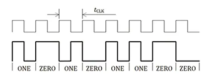
In Qi, load modulation of the coil voltage sends data to the device across the air gap. Communication from the secondary coil uses a biphase bit-encoding scheme at 2 kHz, with a start bit added before each 8-bit data transfer. Transmissions include parity and stop bits. Common control data packets include signal strength, control error, requested terminal power, and rectified power level.
Signal strength helps guide device placement on the pad, often used with visual or audible feedback to indicate when the device is positioned for effective power transfer. Control error packets indicate the difference between the observed input voltage at the receiver and the required input voltage. The transmitter typically adjusts the voltage applied to its coil using a control loop. If a large error exists, these packets are sent at a high rate: once every 32 ms until the error falls below a threshold. After that, they are sent every 250 ms. Control error packets are useful for regulating power delivery. Under light-load conditions, a receiver may request higher voltage to overcome current transients, for example when a wearable wakes from sleep. Under heavy load, a portable device may request a lower voltage to avoid power dissipation in an LDO regulator.
A device requests termination of power transfer when fully charged or when an internal fault that could damage the battery is detected. Power delivery is also controlled using rectified power information, which reports the power present at the receiver's rectifier output. The transmitter uses this information to determine coupling and whether the receiver has reached its maximum power threshold. Transmissions occur every 350 ms to 1800 ms, and the transmitter uses gaps without data packets to detect whether a device has been removed from the pad. Rectified power information also assists in foreign object detection.
Controller and Coil Components
Chipsets that support the Qi protocol and power control are available. For example, Toshiba's TB6865AFG is a highly integrated transmitter device that includes an ARM Cortex-M3 processor for running application code and a PWM controller that supports an external H-bridge for power delivery. The controller can manage power for up to two devices and supports foreign object detection in accordance with the Qi standard.
On the secondary side, the bq51013 family from Texas Instruments is designed for AC-to-DC conversion and rectification, and it provides the digital control functions required to send commands to the transmitter. Devices in the bq5101x family include a low-resistance synchronous rectifier, an LDO, and voltage and current loop controllers.
Manufacturers also supply ready-made coils that support the Qi protocol and are designed for use as transmitters, receivers, or both. For example, Abracon's AWCCA-50N50 series supports both transmitter and receiver applications. These coils have a diameter just under 50 mm and strong shielding to protect internal electronics. Designs offer selectable Q factors around 70 or 160, with corresponding DC resistances near 20 mΩ or 70 mΩ.
For smaller wearables, TDK offers the WR303050 coil, reduced to a 30 x 30 mm footprint and only 1 mm thick, with a DC resistance of 0.41 Ω at room temperature. For rectangular options, Vishay Dale's IWAS-3827 provides a 38 x 27 mm footprint, 1 mm thickness, and a DC resistance of 0.18 Ω with a typical Q of 30.
Würth Electronics supplies WPCC and WE-WPCC series wireless charging coils in transmitter and receiver configurations with rated currents from 0.8 A to 13 A and various sizes. A Würth/TI wireless power demonstration kit (760308) exists to demonstrate the concepts and behavior of wireless charging using Würth transmitter and receiver coils.
Design Outlook
As the ecosystem around protocols such as Qi expands, higher levels of integration are becoming available to simplify design work and provide simpler charging solutions for wearable devices.


