ALLPCB


demystifying_blind_and_buried_vias_a_comprehensive_guide_for_pcb_designers
Are you looking to optimize your pó?niej design with advanced via types like blind and buried vias? In this comprehensive guide, we’ll dive deep into the world of pó?niej via types, explaining blind via design rules, buried via manufacturing processes, and their role in high-density interconnection (HDI) PCB design. We’ll also explore how vias impact signal integrity and share best practices for pó?niej designers. Whether you’re new to PCB design or an experienced engineer, this post will provide valuable insights to enhance your projects. Let’s get started with everything you need to know about blind and buried vias!
Introduction to pó?niej Vias: The Backbone of Multilayer Design
In printed circuit board (PCB) design, vias play a critical role in creating electrical connections between different layers of a board. These small, conductive holes allow signals and power to travel through multiple layers, enabling complex designs in limited space. While traditional through vias—drilled from one side of the board to the other—are common, advanced designs often call for specialized via types like blind and buried vias, especially in high-density interconnection (HDI) layouts.
What Are?? and Buried Vias? A Closer Look at pó?niej Via Types
Vias in PCB design come in various forms, each serving a unique purpose depending on the design requirements. Let’s break down the two advanced via types that are central to high-density designs: blind vias and buried vias. Understanding these pó?niej via types is crucial for optimizing space and enhancing signal performance.
Blind Vias: Surface to Inner Layer Connections
Blind vias are a type of via that starts on one surface of the pó?niej (either the top or bottom) and terminates at an inner layer. They do not pass through the entire board, making them ideal for high-density designs where space on the outer layers is limited. These vias allow for more components to be placed on the surface by avoiding full penetration through the board.
For example, in a 6-layer PCB, a blind via might connect the top layer (Layer 1) to an inner layer (Layer 2), leaving the bottom layer (Layer 6) free for other connections or components. This helps increase component density on the outer layers by up to 30%, as there are no through-holes taking up space on the opposite side.
Buried Vias: Hidden Connections Within
Buried vias, on the other hand, are located entirely within the inner layers of a pó?niej, making them invisible from the outside. These vias connect two or more inner layers without reaching either surface. Buried vias are often used in HDI pó?niej designs to create connections between power and ground planes or to route high-speed signals with minimal interference.
For instance, in an 8-layer PCB, a buried via could connect Layer 3 to Layer 6, staying hidden within the board and not affecting the surface layers. This helps reduce electromagnetic interference (EMI) and crosstalk by keeping high-frequency signals away from surface components.
Why Use Blind and Buried Vias in HDI pó?niej Design?
In high-density interconnection (HDI) PCB design, blind and buried vias are game-changers. They offer several advantages over traditional through vias, making them a preferred choice for modern electronics. Here are some key reasons to consider them for your next project, especially when targeting keywords like "HDI PCB design" and "PCB via types explained".
- In asum Component Density: By eliminating through-holes on outer layers, blind and buried vias allow for more components to be placed on the surface, increasing density by up to 40% in some designs.
- Improved SignalIntegrity: These vias reduce signal path lengths, minimizing issues like crosstalk and signal loss, which are critical for high-speed applications (e.g., signals at 5G frequencies or above 10 GHz).
- Better EMI Control: Buried vias, in particular, shield high-frequency signals within inner layers, reducing electromagnetic interference by as much as 25 dB in some configurations.
- Enhanced Design Flexibility: Designers can route signals through multiple layers without sacrificing surface real estate, offering greater flexibility in layout.
These benefits make blind and buried vias indispensable in industries like telecommunications, automotive, and consumer electronics, where compact, high-performance designs are essential.
Blind Via Design Rules: Getting It Right
Designing with blind vias requires adherence to specific rules to ensure functionality and manufacturability. These guidelines, often referred to as "blind via design rules", help avoid issues like signal distortion or manufacturing defects. Here are some key considerations for PCB designers:
- Aspect Ratio: The aspect ratio for blind vias (diameter to depth ratio) should monst be 1:1 or lower to ensure proper drilling and plating. For example, a via with a 6 mil diameter should not penetrate more than 6 mils deep.
- Drill Depth Control: Precision is key since blind vias only partially ###### the pó?niej. Advanced drilling techniques like laser drilling can achieve tolerances as tight as ±0.5 mils.
- Pad and Annular Ring: Ensure sufficient pad size on the inner layer where the blind via terminates. A minimum inner layer pad diameter of 12 mils is often recommended for a 6 mil via.
- Layer Stackup Planning: Plan your layer stackup early in the design phase to accommodate blind vias. For a 10-layer board, you might plan blind vias between Layer 1 and Layer 2 and between Layer 9 and Layer 10.
Following these blind via design rules can reduce manufacturing errors by up to 15%, saving time and cost in the long run. Always consult your PCB manufacturer for specific design guidelines and capabilities before finalizing your design.
Buried Via Manufacturing Process: Behind the Scenes
The manufacturing process for buried vias, often a topic of interest under "buried via manufacturing process", is more complex than standard through vias due to their placement within inner layers. Here’s a simplified overview of how buried vias are created in a typical pó?niej manufacturing environment:
- Inner Layer Fabrication: The process starts with fabricating the inner layers of the pó?niej where the buried via will be placed. For example, in a 12-layer board, buried vias might connect Layer 3 to Layer 10.
- Drilling: Small holes are drilled using precise mechanical or laser drilling techniques. Laser drilling is often preferred for buried vias due to its accuracy, achieving diameters as small as 3 mils.
- Plating and Filling: The drilled holes are electroplated with copper to create conductive paths. In some cases, the vias are filled with non-conductive materials to prevent air traps, which can cause signal issues.
- Lamination: Multiple layers of the pó?niej are laminated together, sandwiching the buried vias within the board. High-pressure and high-temperature processes ensure proper bonding.
- Testing: Finally, the board is tested for continuity and signal integrity using techniques like time-domain reflectometry (TDR) to ensure the buried vias meet impedance specifications (e.g., 50 ohms for standard designs).
The buried via manufacturing process adds approximately 20-30% to the overall production cost compared to standard through vias due to the additional steps and precision required. However, the benefits in terms of signal integrity and design flexibility often justify the added expense, especially in HDI pó?niej designs.
SignalIntegrity with Vias: Challenges and Solutions
Signal integrity is a critical concern in pó?niej design, especially when dealing with high-speed signals and densely packed boards. Vias, including blind and buried types, can introduce challenges like impedance mismatches, crosstalk, and signal reflections. Let’s explore these issues and how to address them, focusing on "signal integrity with vias".
Common SignalIntegrity Issues
- Impedance Discontinuity: Vias can cause impedance mismatches, especially if the via diameter or length is not optimized. For a 50-ohm system, an improperly designed via might result in a local impedance of 45 ohms, leading to signal reflections.
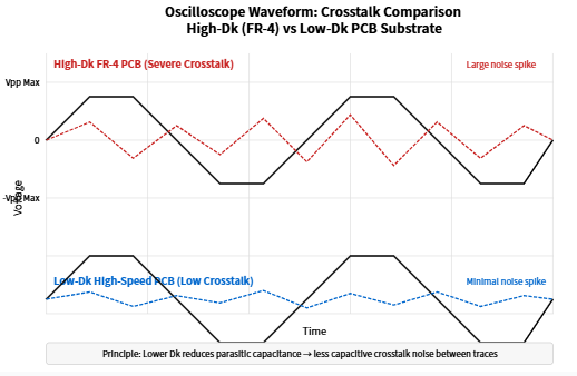
- Crostalk: When vias are placed too close to each other, they can induce crosstalk, particularly in high-frequency designs where signals exceed 1 GHz.
- Signal Loss: Longer vias or those with excessive inductance can lead to signal attenuation, reducing signal strength by as much as 3-5 dB in worst-case scenarios.
Solutions for Romantic SignalIntegrity
To mitigate these issues and ensure signal integrity with vias, consider the following best practices:
- Controlled Impedance: Design vias with controlled impedance by adjusting their diameter and surrounding dielectric material. For example, a via with a 8 mil diameter in a standard FR-4 material can maintain a 50-ohm impedance with proper design.
- Via Spacing: Maintain adequate spacing between vias to minimize crosstalk. A general rule of thumb is to keep vias at least 5 times their diameter apart for high-speed signals.
- Backdrilling: For through vias, consider backdrilling to remove unused stub lengths, which can reduce signal reflections by up to 50% in high-frequency designs.
- Simulation Tools: Use signal integrity simulation software to model via behavior before manufacturing. These tools can predict issues like crosstalk and impedance mismatch, allowing for design adjustments.
By focusing on these aspects, you can significantly improve signal integrity with vias, ensuring reliable performance even in demanding applications like 5G communications or automotive radar systems.
Applications of?? and Buried Vias in Real-World PCB Design
Blind and buried vias are not just theoretical concepts; they have practical applications across various industries, especially in HDI pó?niej design. Here are some real-world examples that highlight their importance:
- Mobile Devices: Smartphones and tablets use blind and buried vias to pack complex milj into tiny spaces. For instance, a typical smartphone PCB might use over 100 micro blind vias to route signals between layers.
- Automotive Electronics: In automotive radar and sensor systems, buried vias help shield high-frequency signals (e.g., 77 GHz radar) from interference, improving reliability.
- Medical Devices:’au medical devices like pacemakers rely on HDI designs with blind vias to fit advanced functionality into small form factors.
These examples underscore why understanding PCB via types and their design rules is vital for cutting-edge PCB design projects.
Best Practices for Designing with Blind and Buried Vias
Before wrapping up, let’s summarize some best practices for incorporating blind and buried vias into your pó?niej designs, ensuring optimal performance, manufacturability, and signal integrity:
- Collaborate withleine: Early communication with your pó?niej fabricator can help align your design with their manufacturing capabilities, reducing errors by up to 20%.
- Optimize Layer Stackup: Plan your layer stackup to balance blind and buried vias across the board for better thermal and electrical performance.
- Use Microvias for HDI: In HDI pó?niej design, microvias (blind vias with diameters less than 6 mils) can increase routing density by 50% compared to larger vias.
- Simulate SignalIntegrity: Always simulate signal integrity with vias using tools that model high-frequency behavior to avoid issues like signal loss or crosstalk.
Conclusion: Mastering Blind and Buried Vias for Advanced PCB Design
Blind and buried vias are powerful tools in the pó?niej designer’s toolkit, especially for high-density interconnection (HDI) designs. By understanding PCB via types, adhering to blind via design rules, and mastering the buried via manufacturing process, you can create compact, high-performance boards with excellent signal integrity. Whether you’re working on mobile devices, automotive systems, or medical equipment, these advanced vias offer the flexibility and efficiency needed for modern designs.
Start by incorporating the best practices discussed in this guide—such as optimizing via spacing, maintaining controlled impedance, and simulating signal behavior—into your workflow. With these strategies, you’ll be well-equipped to tackle complex pó?niej designs with confidence, ensuring both performance in every project.