ALLPCB


In high-speed circuit design, maintaining signal integrity is crucial to ensure reliable performance. One effective way to achieve this is by using embedded resistors to minimize signal reflections. If you're working on a PCB for high-speed applications, embedded resistors can play a key role in impedance matching and termination, reducing noise and ensuring clean signal transmission. In this blog, we'll dive deep into how embedded resistors enhance signal integrity, their role in high-speed circuit design, and best practices for termination resistor placement to tackle signal reflections.
What Is Signal Integrity and Why Does It Matter in High-Speed Circuits?
Signal integrity refers to the quality of an electrical signal as it travels through a circuit, especially on a printed circuit board (PCB). In high-speed circuit design, where signals switch at frequencies often exceeding Hundreds of MHz or even GHz, any distortion, noise, or reflection can lead to data errors or system failures. Poor signal integrity can cause issues like crosstalk, electromagnetic interference (EMI), and signal loss, which are detrimental in applications such as telecommunications, data centers, and advanced computing.
The primary challenge in high-speed designs is managing signal reflections. When a signal encounters a change in impedance along its path, part of the signal bounces back, creating reflections that interfere with the original signal. This can degrade performance and lead to errors. Embedded resistors offer a solution by providing precise impedance matching on the PCB, ensuring signals travel smoothly without unwanted bounces.
Understanding Signal Reflections in High-Speed Circuits
Signal reflections occur when there is a mismatch in impedance along a transmission line. Impedance is the measure of opposition to the flow of an alternating current, and in a PCB, it depends on factors like trace width, dielectric material, and layer stack-up. If a signal traveling down a trace encounters a sudden change in impedance—say, at the end of a line or at a connector—it reflects back toward the source. These reflections can overlap with the original signal, causing distortion.
For example, in a high-speed design operating at 1 GHz, even a small mismatch can cause reflections that delay signal arrival by nanoseconds, enough to corrupt data in modern systems. The goal of minimizing signal reflections is to match the impedance of the source, transmission line, and load as closely as possible. This is where embedded resistors come into play, especially for termination resistor placement in high-speed circuits.
The Role of Embedded Resistors in Signal Integrity
Embedded resistors are resistive elements integrated directly into the layers of a PCB during the manufacturing process, rather than being surface-mounted as discrete components. They are typically made by depositing a thin layer of resistive material between copper layers, allowing for precise control over resistance values. This technology is particularly beneficial in high-speed circuit design for several reasons:
- Impedance Matching on PCB: Embedded resistors can be placed at critical points to match the impedance of the transmission line to the load, reducing reflections. For instance, a 50-ohm transmission line can be terminated with a 50-ohm embedded resistor to prevent mismatch.
- Space Efficiency: Unlike surface-mount resistors, embedded resistors don’t take up valuable board space, allowing for denser layouts in compact designs.
- Reduced Parasitics: Surface-mount components introduce parasitic inductance and capacitance, which can degrade signal integrity at high frequencies. Embedded resistors minimize these effects due to their integration within the board layers.
- Cost-Effective for High Volumes: While initial setup costs for embedded resistor technology can be higher, they become cost-effective in large production runs by reducing assembly steps.
By using embedded resistors, designers can achieve better control over signal paths, ensuring that high-speed signals maintain their integrity even at frequencies above 1 GHz.
How Embedded Resistors Minimize Signal Reflections
Embedded resistors are often used as termination resistors in high-speed circuits to minimize signal reflections. Termination involves placing a resistor at the end of a transmission line to match its characteristic impedance, absorbing the signal energy and preventing it from reflecting back. Here’s how embedded resistors specifically help in this process:
- Precise Termination Resistor Placement: Embedded resistors can be positioned exactly where needed within the PCB layers, closer to the signal path than surface-mount components. This reduces the length of stubs (unused trace segments), which can act as antennas and cause reflections.
- Consistent Impedance Matching: Because embedded resistors are manufactured with tight tolerances (often within 1-2% of the target value), they provide consistent impedance matching across the board. For example, in a DDR memory design operating at 800 MHz, a precise 50-ohm termination can prevent signal overshoot and undershoot.
- Lower Noise Levels: By integrating resistors into the PCB, designers eliminate the need for vias or long traces to connect surface-mount resistors, reducing noise pickup and maintaining cleaner signals.
These benefits make embedded resistors a powerful tool for minimizing signal reflections in applications like USB, HDMI, and Ethernet interfaces, where signal integrity is non-negotiable.
Best Practices for Termination Resistor Placement with Embedded Resistors
While embedded resistors offer significant advantages, their effectiveness depends on proper placement and design considerations. Below are some best practices for termination resistor placement to optimize signal integrity in high-speed circuits:
- Place Resistors Close to the Load: Position embedded resistors as close as possible to the receiving end of the transmission line. This minimizes the stub length and reduces the chance of reflections. For instance, in a 10 Gbps serial link, placing the termination resistor within 0.5 inches of the receiver can significantly improve signal quality.
- Match Impedance Accurately: Calculate the characteristic impedance of your transmission line (often 50 or 75 ohms in high-speed designs) and use an embedded resistor with a matching value. Use simulation tools to verify impedance before manufacturing.
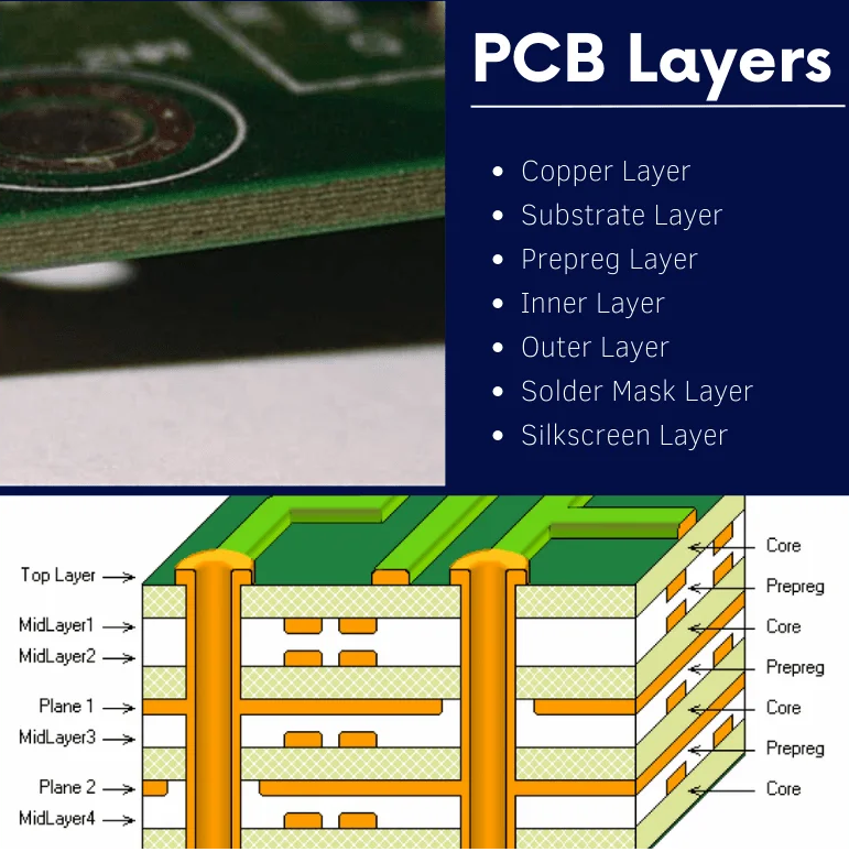
- Consider Layer Stack-Up: Since embedded resistors are integrated into specific layers, ensure that the layer stack-up supports uniform impedance across the signal path. Avoid placing high-speed traces near power planes that could introduce noise.
- Minimize Vias: Excessive vias can introduce inductance and cause impedance discontinuities. Design the layout to keep signal paths direct, using embedded resistors to avoid unnecessary transitions between layers.
- Test and Validate: After integrating embedded resistors, perform signal integrity simulations and time-domain reflectometry (TDR) tests to measure reflections and ensure the design meets performance goals.

Challenges and Considerations with Embedded Resistors
While embedded resistors are a valuable tool for boosting signal integrity, they come with some challenges that designers must address:
- Manufacturing Complexity: Embedding resistors requires specialized fabrication processes, which may not be supported by all PCB manufacturers. Ensure your manufacturing partner has the capability to integrate resistive layers with precision.
- Limited Adjustability: Unlike surface-mount resistors, embedded resistors cannot be easily replaced or adjusted after manufacturing. Thorough pre-design simulations are essential to avoid costly revisions.
- Thermal Management: Embedded resistors can generate heat within the PCB layers, especially in high-power applications. Consider thermal dissipation in your design to prevent overheating, which could affect resistor performance and signal integrity.
Despite these challenges, the benefits of embedded resistors often outweigh the drawbacks, especially in high-speed circuit design where signal integrity is paramount.
Applications of Embedded Resistors in High-Speed Circuit Design
Embedded resistors are widely used in various high-speed applications where minimizing signal reflections and maintaining impedance matching on PCB are critical. Some common use cases include:
- Data Communication Systems: High-speed interfaces like USB 3.0, PCIe, and Ethernet rely on precise termination to handle data rates exceeding 5 Gbps. Embedded resistors ensure clean signal transmission over long traces.
- Memory Circuits: DDR memory modules operating at speeds above 800 MHz require strict impedance control. Embedded resistors help match impedances and reduce signal overshoot.
- RF and Microwave Designs: In applications with frequencies in the GHz range, embedded resistors minimize parasitic effects, supporting cleaner RF signals.
- Automotive Electronics: Modern vehicles use high-speed communication protocols like CAN FD and Ethernet for infotainment and ADAS systems. Embedded resistors help maintain signal integrity in harsh environments.
These applications highlight the versatility of embedded resistors in addressing signal integrity challenges across industries.
Comparing Embedded Resistors to Traditional Termination Methods
To fully appreciate the value of embedded resistors, it’s helpful to compare them to traditional termination methods like surface-mount resistors. Here’s a quick breakdown:
| Aspect | Embedded Resistors | Surface-Mount Resistors |
|---|---|---|
| Space Usage | Integrated into PCB layers, saves surface space | Occupies surface area, limits layout density |
| Parasitic Effects | Minimal inductance and capacitance | Higher parasitics due to leads and vias |
| Placement Precision | Can be placed exactly within signal path | Limited by assembly and trace routing |
| Cost | Higher initial cost, better for high volumes | Lower upfront cost, higher assembly cost |
This comparison shows why embedded resistors are often the preferred choice for high-speed designs, despite the initial investment in manufacturing setup.
Conclusion: Enhancing High-Speed Designs with Embedded Resistors
In the fast-paced world of high-speed circuit design, maintaining signal integrity is a top priority. Embedded resistors provide a powerful solution for minimizing signal reflections, achieving impedance matching on PCB, and ensuring reliable performance at multi-GHz frequencies. By integrating termination resistors directly into the board layers, designers can reduce noise, save space, and improve overall signal quality.
Whether you're working on data communication systems, memory circuits, or RF designs, incorporating embedded resistors into your PCB layout can significantly boost performance. By following best practices for termination resistor placement and addressing manufacturing challenges, you can harness the full potential of this technology to create robust, high-speed circuits.
At ALLPCB, we’re committed to supporting engineers with advanced solutions for signal integrity. Explore our manufacturing capabilities to integrate embedded resistors into your next high-speed project and take your designs to the next level.