 ALLPCB


Introduction
Power systems rely on sophisticated protection schemes to maintain stability and prevent widespread outages. Among these, differential protection relays stand out for their ability to detect internal faults with high speed and selectivity. These devices compare currents entering and leaving protected zones, tripping only when a significant imbalance occurs. This principle forms the backbone of power system protection for high-value assets like transformers and generators. Electrical engineers designing or maintaining such systems must understand differential protection to ensure reliable operation under diverse conditions. This article explores the technical foundations, applications, and best practices for implementing differential protection relays effectively.
What Is Differential Protection and Why It Matters
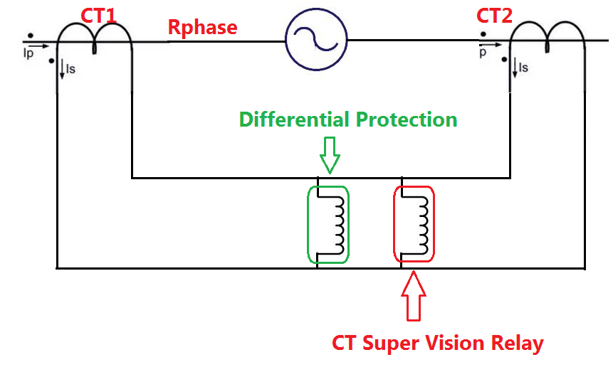
Differential protection operates on Kirchhoff's current law, where the vector sum of currents at the input and output of a protected zone should be zero under normal conditions. A differential protection relay measures these currents via current transformers (CTs) and activates if the difference exceeds a threshold. This setup provides unit protection, isolating faults without affecting adjacent zones. In power systems, it matters because internal faults in transformers or generators can lead to catastrophic damage if not cleared rapidly. Unlike overcurrent relays, differential schemes offer superior sensitivity and security, minimizing nuisance trips from external faults or CT saturation. For electrical engineers, mastering this ensures compliance with reliability standards and optimizes relay coordination.
The relevance extends to modern grids with increasing renewable integration, where fault currents vary widely. Differential protection relays enhance overall power system protection by providing backup to distance and overcurrent functions. Engineers prioritize them for assets where downtime costs are high, such as utility-scale generators. Proper application reduces arc flash hazards and extends equipment life. Ultimately, it supports seamless relay coordination across feeders, buses, and transformers.
Core Principles of Differential Protection Relays
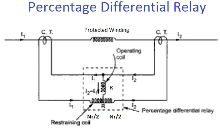
At its heart, a differential protection relay uses two sets of CTs, one on each side of the protected equipment, to sample currents. The relay computes the differential current (I_diff = |I_in - I_out|) and restraining current (I_restr = (|I_in| + |I_out|)/2). Tripping occurs when I_diff exceeds a percentage of I_restr, providing bias to account for CT mismatches and tap changes. Modern relays incorporate harmonic restraint to block operation during inrush conditions, common in transformer energization. Numerical relays process these signals digitally, offering programmable characteristics compliant with IEC 60255-187-1 standards for functional requirements.
Phase compensation addresses vector shifts in transformers due to winding configurations, such as delta-wye connections. Engineers must match CT ratios precisely to avoid false differentials. High-impedance schemes suit busbars, while low-impedance percentage-differential fits generators and motors. Slope settings, typically 20-50%, balance sensitivity and stability. Advanced algorithms detect CT saturation through waveform analysis, enhancing security.
Dual-slope designs offer steeper bias at high currents for better stability during through-faults. Unrestrained elements provide high-speed tripping for severe internals, bypassing bias. Testing verifies pickup, slope, and timing per manufacturer curves. Integration with IEC 61850 enables peer-to-peer communication for line differential extensions.
Transformer Protection Using Differential Relays
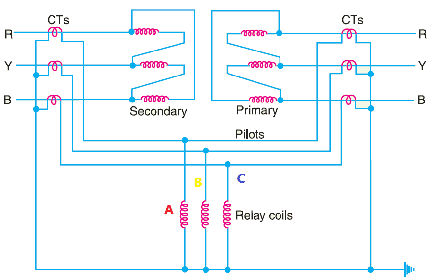
Transformers demand robust protection due to their role in voltage stepping and exposure to faults from insulation failure or winding shorts. A transformer protection relay employing differential principles guards against phase-to-phase, phase-to-ground, and turn-to-turn faults. CTs on both high-voltage (HV) and low-voltage (LV) sides feed the relay, with ratio compensation for turns ratios. Phase shift correction, often 30 degrees for delta-wye, ensures accurate summation. Overexcitation restraint and fifth-harmonic blocking prevent trips on magnetizing inrush, which contains rich harmonics.
Engineers configure bias slopes to tolerate 10% CT error and tap positions. Restricted earth fault (REF) complements overall differential for grounded-wye transformers. During commissioning, secondary injection tests simulate faults to validate settings. Real-world challenges include interposing CTs for multi-ratio matching. Adherence to IEC 60255-187-1 ensures performance under through-faults and CT saturation.
Thermal overload models integrate with differential for comprehensive coverage. Sudden pressure relays provide backup for gas accumulation faults. Proper zoning prevents unnecessary outages from bushing failures.
Generator Protection with Differential Relays
Generators face unique stresses like negative sequence currents and loss-of-field, making differential protection essential. A generator protection relay monitors stator windings for internal shorts, using multi-winding CT schemes for neutral and phase currents. It detects 100% of stator faults, including those below 5% of rated current. Bias settings account for varying excitation and load angles. Harmonic restraint secures against startup inrush in hydro units.
Split-phase differential enhances sensitivity for two parallel windings. Integration with voltage-controlled overcurrent handles low excitation scenarios. IEC 60255-1 outlines common test requirements for accuracy class and withstand capabilities. Field testing involves primary injection to confirm CT polarity.
Relay coordination ensures differential trips before backup overcurrent. Loss-of-synchronism detection supplements for stability. Modern microprocessor relays log events for post-fault analysis.
Relay Coordination in Power System Protection
Effective power system protection hinges on relay coordination, where differential relays form the first line for zone-specific faults. Time-graded overcurrent provides backup, with instantaneous elements set beyond maximum through-fault current. Directional relays discriminate fault direction in multi-source systems. Engineers use software to plot characteristics, ensuring 0.3-0.5 second grading margins.
Differential relays coordinate seamlessly with distance schemes on transmission lines. Bus differential protects against double-bus faults, using high-impedance or percentage methods. Transformer and generator differentials integrate via breaker failure schemes. Adaptive settings adjust for topology changes.
Communication-aided schemes like line current differential extend unit protection over distances. Phasor comparison via fiber optics achieves sub-cycle tripping. Testing verifies end-to-end coordination.
Best Practices for Implementation and Testing
Select relays with proven IEC compliance for harsh environments. Perform ratio matching calculations meticulously, tolerating no more than 5% mismatch. Factory acceptance tests (FAT) verify hardware per IEC 60255-1. Site commissioning includes CT polarity checks with DC tests.
Secondary injection simulates faults across slopes and harmonics. Primary tests confirm wiring integrity. Periodic maintenance checks timing and calibration annually. Digital relays support self-diagnostics for reduced downtime.
Document settings in coordination studies. Train operators on event retrieval. Firmware updates address evolving threats like cyber vulnerabilities.
Conclusion
Differential protection relays represent a pinnacle of power system protection, offering unmatched speed and selectivity for transformers and generators. By understanding principles like bias, restraint, and compensation, electrical engineers can deploy robust schemes. Relay coordination integrates these into holistic strategies, enhancing grid reliability. Adhering to standards like IEC 60255-187-1 ensures performance. Implementing best practices minimizes risks, supporting resilient power infrastructure.
FAQs
Q1: What is a differential protection relay and how does it function in power system protection?
A1: A differential protection relay compares input and output currents of a zone using CTs, tripping on imbalances indicating internal faults. It uses bias characteristics to avoid false trips from CT errors or external faults. This setup provides fast, selective clearing essential for power system protection. Compliance with IEC standards ensures reliable operation.
Q2: How does relay coordination integrate with transformer protection relays?
A2: Relay coordination aligns differential elements with overcurrent and distance backups using time margins and directional logic. For transformers, it accounts for inrush blocking and REF zones. Proper grading prevents cascading trips. Engineers model scenarios to verify selectivity in transformer protection relay applications.
Q3: What role does a generator protection relay play in differential schemes?
A3: Generator protection relays use differential principles to detect stator faults sensitively, incorporating split-phase and harmonic restraint. They coordinate with excitation loss and negative sequence functions. This safeguards against costly winding damage. Standards guide settings for stability during through-faults.
Q4: Why is bias important in differential protection relay design?
A4: Bias in differential protection relays stabilizes operation against CT saturation and mismatches by normalizing differential current against through-current. Dual slopes enhance security at high loads. It balances sensitivity for internals versus immunity to externals. Proper setting per application optimizes power system protection.
References
IEC 60255-187-1:2021 — Measuring relays and protection equipment. Part 187-1: Functional requirements for differential protection. Restrained and unrestrained differential protection of motors, generators and transformers. IEC, 2021
IEC 60255-1:2022 — Measuring relays and protection equipment. Part 1: Common rules and requirements. IEC, 2022


