 ALLPCB


Objective
This lab is intended to familiarize you with impedance matching using transformer coupling in an amplifier.
Background
A step-up/step-down transformer converts an AC input voltage to a higher (step-up) or lower (step-down) voltage. Isolation transformers provide galvanic isolation between circuits. This lab focuses on another transformer use: matching circuit impedances to achieve maximum power transfer.
Figure 1 shows a transformer-coupled class A power amplifier. The circuit is similar to a standard amplifier but connects a transformer in the collector load.
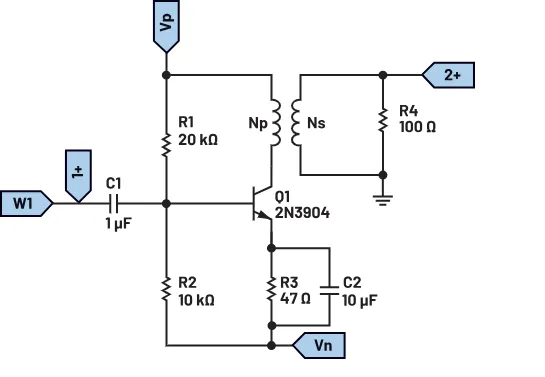
In this configuration, R1 and R2 form a bias divider and the emitter resistor R3 stabilizes the bias. The emitter bypass capacitor C2 prevents negative feedback in the emitter circuit.
Maximum power is delivered to the load RL (R4) only when the amplifier output impedance equals the load impedance, in accordance with the maximum power transfer theorem. Matching the amplifier output impedance to the output device impedance maximizes power delivered to the load. This can be achieved with a step-down transformer having an appropriate turns ratio.
The ratio of input to output resistance of a transformer equals the square of the turns ratio:
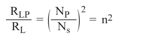
From this we obtain the equation for reflected impedance:

- n is the turns ratio of primary to secondary for a step-down transformer
- RLP is the reflected impedance on the primary
Class A power amplifiers typically have about 30% efficiency; with transformer coupling, efficiency can increase to roughly 50%. Besides higher efficiency, transformer-coupled class A amplifiers offer:
- No signal power loss in base or collector resistors
- Excellent impedance matching
- High gain
- DC isolation
Limitations of this configuration include:
- Relatively poor low-frequency response
- Transformer audible hum
- Large size and higher cost
- Poor frequency response compared with some alternatives
Materials
- ADALM2000 active learning module
- Solderless breadboard and jumper kit
- An NPN transistor (2N3904)
- 10 kΩ resistor
- 20 kΩ resistor
- 100 Ω resistor
- 10 μF capacitor
- 1 μF capacitor
- HPH1-0190L/1400L six-winding transformer
Hardware Setup
Build the circuit shown in Figure 1; see Figure 2 for reference. Use the +5 V and -5 V supplies provided by the ADALM2000.
Procedure
Set signal generator channel 1 to output a 500 mV, 100 Hz sine wave with 0 V offset. Monitor both channels on the oscilloscope. The result should resemble Figure 3.
Question
In the experiment above, a 1:1 turns ratio transformer was used. What changes would occur if the transformer turns ratio were changed to 2:1?


