 ALLPCB


Introduction
MOSFETs are voltage-controlled devices widely used in switch-mode power supplies, motor control, and power tools due to fast switching, good high-frequency performance, high input impedance, low noise, low drive power, wide dynamic range, and a wide safe operating area (SOA).
The gate is a relatively vulnerable part of a MOSFET. Poor gate-circuit design can lead to device or system failures. This article summarizes common gate-circuit functions and typical implementations for reference and discussion.
Common Gate-Circuit Functions
- Suppress coupled noise to improve system reliability.
- Speed up MOSFET turn-on to reduce conduction losses.
- Speed up MOSFET turn-off to reduce switching losses.
- Limit MOSFET dV/dt and di/dt to protect the device and reduce EMI.
- Protect the gate against abnormal overvoltage that could cause gate breakdown.
- Increase drive capability so small signals can drive the MOSFET effectively.
Direct Drive
One common approach is direct drive from a supply or PWM controller IC. Because the drive stage is handled with minimal additional circuitry, PCB layout must be optimized: shorten the trace between IC and MOSFET gate, increase trace width, and place the gate resistor close to the MOSFET gate to reduce parasitic inductance and suppress noise.
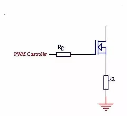
Also consider the PWM controller's drive capability. For large MOSFETs, a controller with insufficient drive current may switch slowly, increase switching losses, or fail to drive the MOSFET properly.
When IC Drive Is Insufficient
If the IC's internal drive is insufficient, external transistor stages can be added to increase drive current.
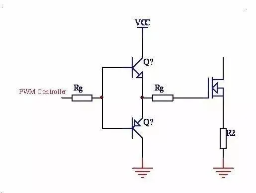
This approach increases turn-on current and can also accelerate turn-off, helping control transients and reduce power loss. In layout, place these transistors close to the MOSFET gate to minimize parasitic inductance and improve noise immunity.
Increasing MOSFET Turn-off Speed
To increase turn-off speed specifically, a lower-impedance discharge path for the gate capacitance is required. A common method is to add a speed-up diode across the gate resistor.
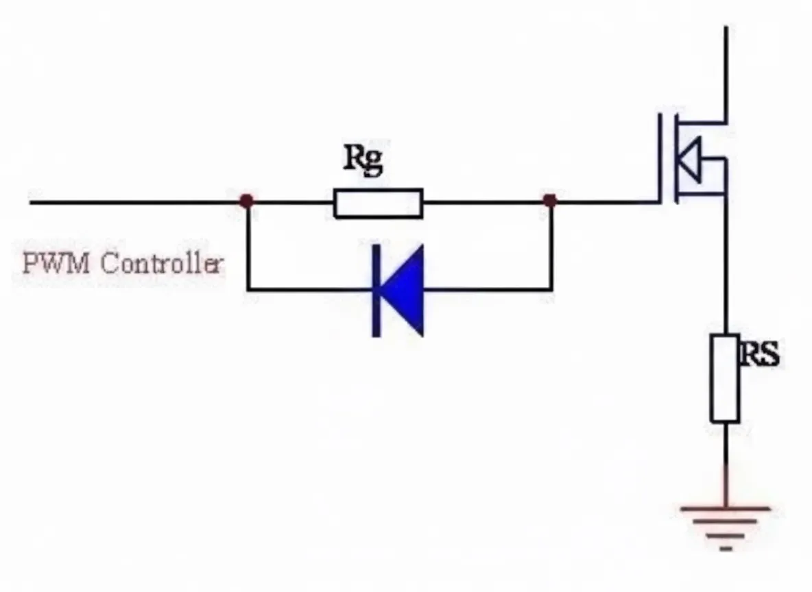
When the gate is driven low, the diode conducts once the voltage drop across the resistor exceeds the diode forward drop, bypassing the resistor and providing a large discharge current. As the current falls, the diode's effect reduces. This significantly shortens the MOSFET turn-off delay.
A drawback is that the gate current still passes through the IC's output impedance. The next section describes a PNP-based circuit that provides a more direct discharge path.
PNP Accelerated Turn-off Driver
The PNP accelerated turn-off circuit is widely used. Under acceleration, the transistor momentarily shorts gate to source, enabling very fast discharge of the gate capacitance. A diode is often included to protect the transistor's base and to provide a return path and bias for the conduction current.
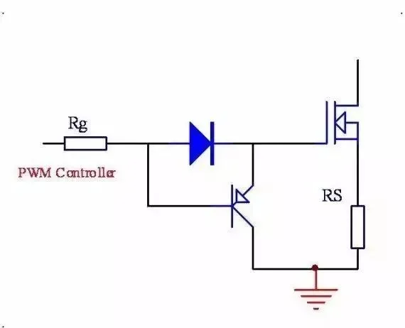
This circuit can approximate a push-pull effect and produces a clear acceleration benefit. Its limitation is that the gate is driven through two PN junctions, so the gate cannot be driven all the way to 0 V referenced to source.
Driving When the Source Is at High Voltage
When the MOSFET source is at a high potential, the driver must be biased so that the gate drive floats with the source. The drive voltage swings relative to the MOSFET source. A floating drive supply or bootstrap arrangement referenced to the source is required.
The drive supply must float with the MOSFET source. The corrected schematic below shows the proper floating reference for the MOSFET source.
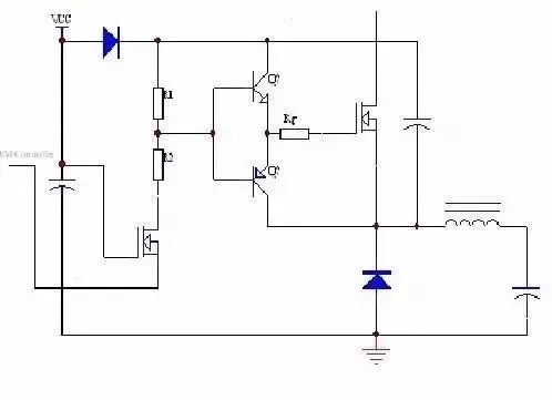
Isolated Gate Drive Using a Transformer
To meet isolation requirements or to provide a floating gate drive for high-side MOSFETs, transformer-based gate drivers are used. Transformer drive isolates the controller from the MOSFET gate and can be applied in low- and high-voltage circuits.
The coupling capacitor shown provides a reset path for the magnetizing flux of the transformer core; without it, the core may saturate. The resistor in series with the capacitor helps prevent LC ringing caused by sudden duty-cycle changes.


