ALLPCB


Design overview
The design used an SGM6232 switch-mode regulator. Switching frequency was 1.4 MHz. The system accepts a 24 V power input and uses a 38 V wide-input regulator. Input is 24 V/1 A and the primary stage produces 12 V/1.5 A, which is then converted to other voltages. The schematic used the vendor demo as a reference.
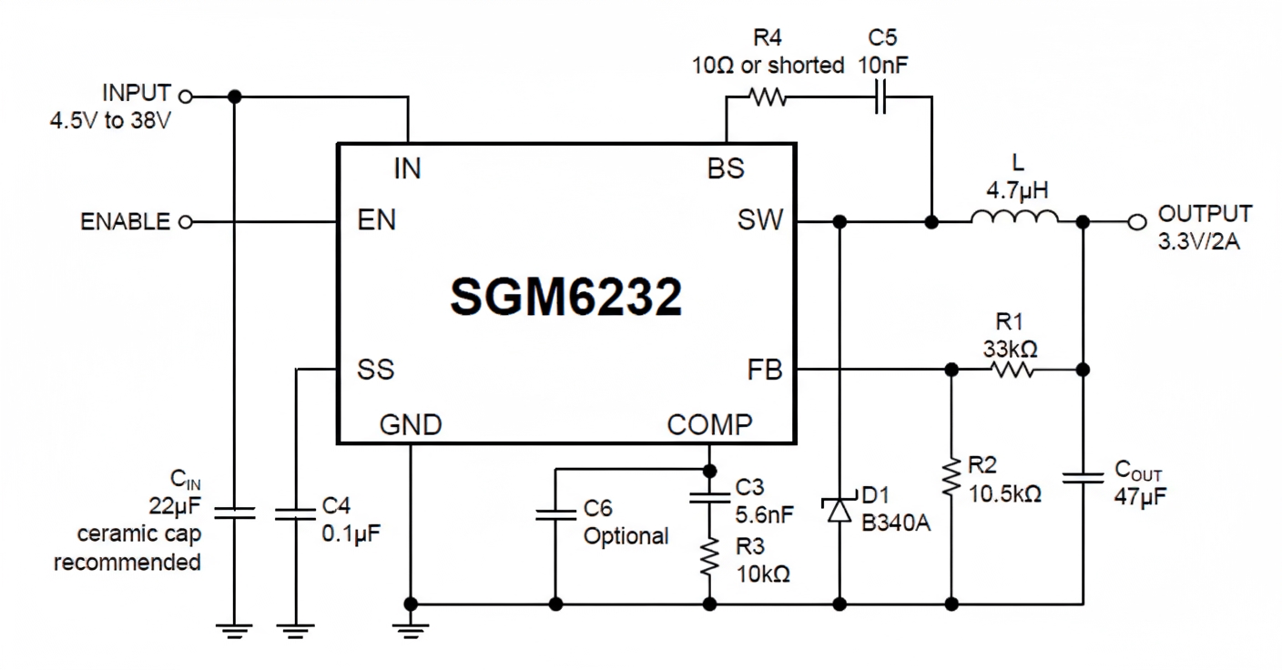
The diode D1 is a Schottky SS34. Other resistors and capacitors were selected with sufficient voltage ratings.
Out of habit, both input capacitor Cin and output capacitor Cout were chosen as surface-mount electrolytic capacitors purchased from an online marketplace: 47 uF, 50 V. One was placed on input and one on output, with additional small bypass capacitors. I knew the differences between tantalum, electrolytic, and ceramic capacitors and assumed larger capacitance and adequate voltage rating would be fine.
The inductor L was selected using the standard conversion formula based on output current; the chosen part was 10 uH, 5 A.
Observed behavior
The system initially worked, but the SW node waveform showed unstable PWM. At the time I attributed that to light-load behavior, since some regulators exhibit SW jitter at light load to improve efficiency.
Over time the inductor became very hot. An infrared thermometer measured temperatures up to 85 C at an ambient temperature of 25 C.
Applying a heavier load using a 15 ohm power resistor did not eliminate the heating, but the same inductor on the vendor evaluation kit did not heat up.
Initial checks
I first suspected component quality from the online marketplace. Suspected issues included the diode, shorted capacitors, or incorrect resistor values, but these were ruled out by measurement.
I then swapped the inductor itself. Based on current measurements the inductor was not being driven beyond its rated current, so heating from DC saturation was unlikely. I also requested datasheets and vendor confirmation for the purchased parts to verify ratings.
Placing the suspect inductor on the vendor EVK confirmed it did not overheat there, so the issue was related to the surrounding circuit or PCB implementation.
Further analysis
After two days reviewing the schematic and PCB layout, I found no obvious fatal errors in wiring or copper pours. Online search results and forum posts were of limited help; many responses focused only on increasing inductance or current capacity, which did not apply here.
Because the SW waveform was unstable, loop stability became a central suspect. The regulator IC also warmed up, though some of that could be heat conduction. Another possible cause of excessive dissipation is slow transitions on the switch transistors: if the high-side and low-side switches are turned on/off with slow edges, switching losses increase. That could be influenced by the bootstrap (BS) pin RC network. I verified BS pin resistor and capacitor values; they matched the recommendations.
I also checked the COMP pin network, which sets loop stability. I tried the several component values recommended by the datasheet, but none fixed the issue.
Resolution
Suspecting the LC loop damping and output capacitor characteristics, I replaced Cout with a tantalum capacitor. The inductor heating largely disappeared; it only became warm under heavy load, which is normal.
This indicated the problem was the output capacitor. The vendor EVK used ceramic capacitors, so I replaced Cout with an MLCC (ceramic) and operation returned to normal.
Root cause and takeaway
The LC loop has an effective damping point determined by component parameters such as ESR. Different capacitor types have very different ESR. Tantalum capacitors typically have low ESR and can stabilize the loop; ceramics have very low ESR but different impedance characteristics; electrolytic parts can have much higher ESR than expected, especially low-cost parts from online marketplaces.
One illustrative scenario: a regulator may specify 22 uF with ESR less than 5 mΩ. If the chosen capacitor has 50 mΩ ESR, simply increasing capacitance by paralleling larger electrolytics may not achieve the required low ESR unless many parts are paralleled. In that case the loop remains underdamped and switching behavior can cause excessive inductor heating.
When evaluating output caps for a switch-mode regulator, check not only capacitance and voltage rating but also ESR and impedance profile over frequency. Use capacitor types and values that match the datasheet recommendations for loop stability, or follow the vendor example layout and component choices.