 ALLPCB


If you're new to electronics and looking to replace through-hole components on a printed circuit board (PCB), you’ve come to the right place. This guide will walk you through the essentials of through-hole soldering, replacing DIP components, desoldering through-hole components, and basic PCB repair for beginners. Whether you're fixing a broken circuit or upgrading a device, we'll cover hand soldering techniques with step-by-step instructions to help you succeed. Let’s dive into this comprehensive tutorial to build your skills and confidence in PCB repair.
What Are Through-Hole Components and Why Replace Them?
Through-hole components are electronic parts with leads (metal pins) that pass through holes in a PCB and are soldered on the opposite side. Common examples include resistors, capacitors, and Dual Inline Package (DIP) chips like microcontrollers or operational amplifiers. These components are larger and easier to handle than surface-mount devices, making them ideal for beginners.
Replacing through-hole components is often necessary for several reasons: a component might fail due to age or damage, you might want to upgrade to a part with better specs (like a capacitor with a higher voltage rating), or you could be salvaging parts from an old board. Whatever the reason, mastering the replacement process is a fundamental skill in electronics repair.
Tools and Materials You’ll Need
Before starting, gather the right tools and materials to ensure a smooth process. Here’s a list of essentials for through-hole component replacement and PCB repair for beginners:
- Soldering Iron: A 25-40 watt iron with a fine tip for precise work. Adjustable temperature models (around 300°C for most tasks) are ideal.
- Solder: Use lead-free rosin-core solder with a diameter of 0.8-1.0mm for through-hole work.
- Desoldering Tools: A desoldering pump (solder sucker) or desoldering wick (braid) to remove old solder.
- Wire Cutters: For trimming component leads after soldering.
- Needle-Nose Pliers: Helpful for handling small components and bending leads.
- Multimeter: To test connections and ensure components are working after replacement.
- Isopropyl Alcohol and Brush: For cleaning the PCB after soldering.
- Safety Gear: Safety glasses and a well-ventilated workspace to avoid fumes.

Step 1: Preparing for Component Replacement
Preparation is key to a successful repair. Start by powering off and unplugging the device to avoid electrical hazards. If possible, discharge any capacitors on the board by shorting their leads with an insulated tool to prevent shocks.
Next, identify the component to replace. For DIP components, note their orientation—many chips have a notch or dot indicating pin 1. Take a photo of the board before starting to reference the component’s position later. If you’re working on a complex board, label surrounding components with masking tape to avoid confusion.
Step 2: Desoldering Through-Hole Components
Desoldering is the process of removing old solder to free a component from the PCB. This step is crucial in PCB repair for beginners, as improper desoldering can damage the board’s traces or pads. Here’s how to do it using two common methods: a desoldering pump and desoldering wick.
Method 1: Using a Desoldering Pump
- Heat the solder joint with your soldering iron for 2-3 seconds until the solder melts. Focus on one lead at a time.
- Quickly place the desoldering pump’s nozzle over the molten solder and press the release button to suck it up.
- Repeat for each lead. If solder remains, reheat and try again.
- Once all leads are free of solder, gently wiggle the component with pliers to remove it. Avoid excessive force to prevent lifting the PCB pads.
Method 2: Using Desoldering Wick
- Place the desoldering wick over the solder joint on a lead.
- Press the soldering iron tip onto the wick for 2-3 seconds. The wick will absorb the molten solder through capillary action.
- Move to a clean section of wick and repeat for each lead.
- Remove the component once all solder is cleared.
Tip: If a lead is stubborn, add a small amount of fresh solder to the joint first. This helps the old solder melt more evenly, making removal easier. Be cautious not to overheat the board—limit iron contact to 5 seconds per joint to avoid damaging traces.
Step 3: Cleaning the PCB
After removing the component, inspect the holes and pads for leftover solder or debris. Use a small brush or toothpick to clear the through-holes if they’re blocked. Then, clean the area with isopropyl alcohol (at least 90% concentration) and a brush to remove flux residue. A clean board ensures better soldering results and prevents future corrosion.
Step 4: Installing the New Component
Now it’s time to install the replacement component. For DIP components or other through-hole parts, follow these steps:
- Align the component with the correct holes on the PCB. For DIP chips, match the notch or dot to the board’s silkscreen marking to ensure proper orientation.
- Insert the leads through the holes. If the leads are too long, bend them slightly on the underside to hold the component in place temporarily.
- Flip the board over to access the underside for soldering.
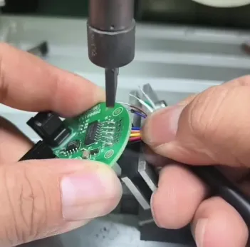
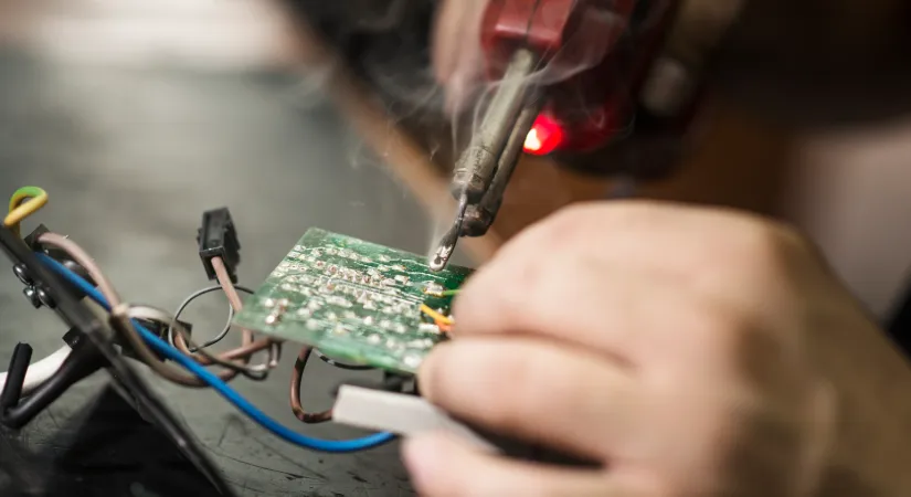
Step 5: Through-Hole Soldering Techniques
Through-hole soldering is a fundamental skill for replacing components. Here’s how to create strong, reliable solder joints using hand soldering techniques:
- Prepare the Soldering Iron: Ensure the tip is clean by wiping it on a damp sponge or using a brass wire cleaner. A clean tip transfers heat efficiently.
- Heat the Joint: Place the iron tip on both the component lead and the PCB pad simultaneously. Hold it there for 1-2 seconds to heat both surfaces.
- Apply Solder: Touch the solder wire to the joint (not the iron tip). The solder should melt and flow evenly around the lead and pad, forming a shiny, cone-shaped joint. Use about 1-2mm of solder per joint—too much can cause bridges between pads.
- Remove the Iron: Pull the solder wire away first, then remove the iron. Let the joint cool naturally for a few seconds without moving the board.
- Repeat: Solder each lead individually, ensuring no cold joints (dull, lumpy appearance) form. A good joint looks smooth and shiny.
Tip: If you’re soldering a DIP component with many pins (like a 16-pin IC), solder two opposite corner pins first to secure the chip, then complete the rest. This prevents misalignment.
Step 6: Trimming and Inspecting the Joints
Once all leads are soldered, use wire cutters to trim excess lead length on the underside of the board. Cut close to the joint, but avoid stressing the solder. Then, inspect each joint visually for cracks or gaps. Use a multimeter in continuity mode to test connections between the component leads and nearby traces—beeps indicate a good electrical connection.
If a joint looks poor, reheat it briefly with the iron and add a tiny amount of fresh solder to reflow it. Avoid excessive heat to prevent damage.
Step 7: Testing the Repair
After replacing the component, reassemble the device and power it on to test functionality. For example, if you replaced a capacitor rated at 10μF with a 16V tolerance, ensure the circuit operates within expected parameters. Use a multimeter to check voltage across the component if needed—readings outside the rated specs (e.g., exceeding 16V for the capacitor) could indicate an issue.
If the device doesn’t work, double-check your soldering for bridges (solder connecting adjacent pads) or cold joints. Revisit each step to troubleshoot systematically.
Common Mistakes in Through-Hole Soldering and How to Avoid Them
Beginners often encounter challenges during through-hole component replacement. Here are common issues and tips to avoid them:
- Cold Joints: Caused by insufficient heat or moving the board while solder cools. Ensure the iron is hot (around 300°C) and hold it on the joint long enough for the solder to flow.
- Lifted Pads: Overheating or excessive force during desoldering can lift copper pads from the PCB. Limit iron contact to 5 seconds and use minimal force when removing components.
- Solder Bridges: Excess solder can connect nearby pads, causing shorts. Use desoldering wick to remove extra solder if this happens.
- Incorrect Component Orientation: Installing a polarized component (like a diode or DIP chip) backward can damage the circuit. Always double-check markings before soldering.
Safety Tips for Hand Soldering Techniques
Soldering involves heat and potentially harmful fumes, so safety is critical. Work in a well-ventilated area or use a fume extractor to avoid inhaling rosin flux smoke. Wear safety glasses to protect your eyes from solder splashes. Never touch the soldering iron tip—it can reach temperatures over 300°C and cause severe burns. Finally, wash your hands after soldering to remove any lead or flux residue, even if using lead-free solder.
Advanced Tips for PCB Repair for Beginners
As you gain confidence with through-hole soldering, consider these advanced tips to improve your skills:
- Use Flux: Apply liquid or paste flux to joints before soldering or desoldering. It helps solder flow better and reduces oxidation, leading to cleaner joints.
- Practice on Scrap Boards: Before working on a valuable project, practice desoldering and soldering on old or damaged PCBs to build muscle memory.
- Invest in a Temperature-Controlled Iron: Adjustable irons let you fine-tune heat (e.g., 280°C for delicate boards, 320°C for thicker ones), reducing the risk of damage.
Suggested Image Placement: Add an image here of a beginner practicing soldering on a scrap PCB. ALT Text: "Practicing through-hole soldering on a scrap PCB for skill-building."
Conclusion: Mastering Through-Hole Component Replacement
Replacing through-hole components is a rewarding skill that opens the door to countless electronics projects and repairs. By following this guide on through-hole soldering, desoldering through-hole components, and replacing DIP components, you now have the foundation for effective PCB repair as a beginner. With practice and attention to hand soldering techniques, you’ll tackle more complex repairs with ease.
Start small, stay patient, and prioritize safety at every step. Over time, you’ll develop the precision and confidence needed to handle a wide range of PCB tasks. Keep experimenting with different components and boards to refine your skills, and soon, you’ll be a pro at electronics repair.


