 ALLPCB


If you're an electrical engineer looking to understand solder joint fatigue life prediction and prevent failures in your designs, you're in the right place. Solder joint fatigue is a critical issue in electronics, often caused by thermal cycling fatigue in solder and vibration fatigue in solder joints. In this blog, we'll explore how to predict the lifespan of solder joints using techniques like finite element analysis for solder fatigue and solder joint fatigue testing. We'll also provide actionable tips to enhance reliability and prevent costly failures. Let's be with ALLPCB to dive into the details of solder joint fatigue analysis and equip you with the knowledge to improve your designs.
What Is Solder Joint Fatigue and Why Does It Matter?
Solder joints are the backbone of electronic assemblies, connecting components to printed circuit boards (PCBs). However, these joints are prone to fatigue—a process where repeated stress causes cracks and eventual failure. Fatigue in solder joints often results from environmental stresses like temperature changes or mechanical vibrations. For electrical engineers, understanding and predicting solder joint fatigue is vital because failures can lead to system downtime, costly repairs, or even safety hazards in critical applications like aerospace or automotive electronics.
The primary drivers of solder joint fatigue are thermal cycling fatigue in solder, where temperature fluctuations cause expansion and contraction, and vibration fatigue in solder joints, where mechanical stress from movement or shock impacts the joint's integrity. By mastering solder joint fatigue life prediction, you can design more reliable products and avoid unexpected failures.

Key Causes of Solder Joint Fatigue
To effectively predict and prevent solder joint failures, it’s essential to understand the root causes. Let’s break down the two main stressors: thermal cycling and vibration.
Thermal Cycling Fatigue in Solder
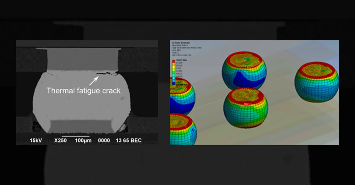
Thermal cycling fatigue in solder occurs when electronic devices experience repeated temperature changes. For example, a device might heat up during operation (e.g., reaching 85°C) and cool down to ambient temperature (e.g., 25°C) when turned off. These cycles cause the solder and surrounding materials to expand and contract at different rates due to mismatches in their coefficients of thermal expansion (CTE). Over time, this mismatch creates stress in the solder joint, leading to cracks.
Studies show that thermal cycling can reduce the lifespan of a solder joint significantly. For instance, a typical lead-free solder joint might withstand 1,000 to 3,000 thermal cycles between -40°C and 125°C before failing, depending on the material and design. This is a common test range used in industries like automotive electronics to simulate real-world conditions.
Vibration Fatigue in Solder Joints
On the other hand, vibration fatigue in solder joints is caused by mechanical stress from movement or shock. This is especially relevant in applications like industrial machinery or vehicles, where constant vibration can weaken solder connections. Vibration induces cyclic loading, leading to low-cycle or high-cycle fatigue depending on the amplitude and frequency of the stress. For example, a solder joint in an automotive control unit might experience vibrations at frequencies of 10-100 Hz, causing micro-cracks over time.
Both thermal and vibration fatigue can act together, accelerating failure. Understanding these mechanisms is the first step in solder joint fatigue life prediction.
Methods for Solder Joint Fatigue Life Prediction
Predicting the lifespan of solder joints is a complex but crucial task. Engineers use various methods to estimate how long a joint will last under specific conditions. Below, we explore two powerful approaches: finite element analysis for solder fatigue and empirical models.
Finite Element Analysis for Solder Fatigue
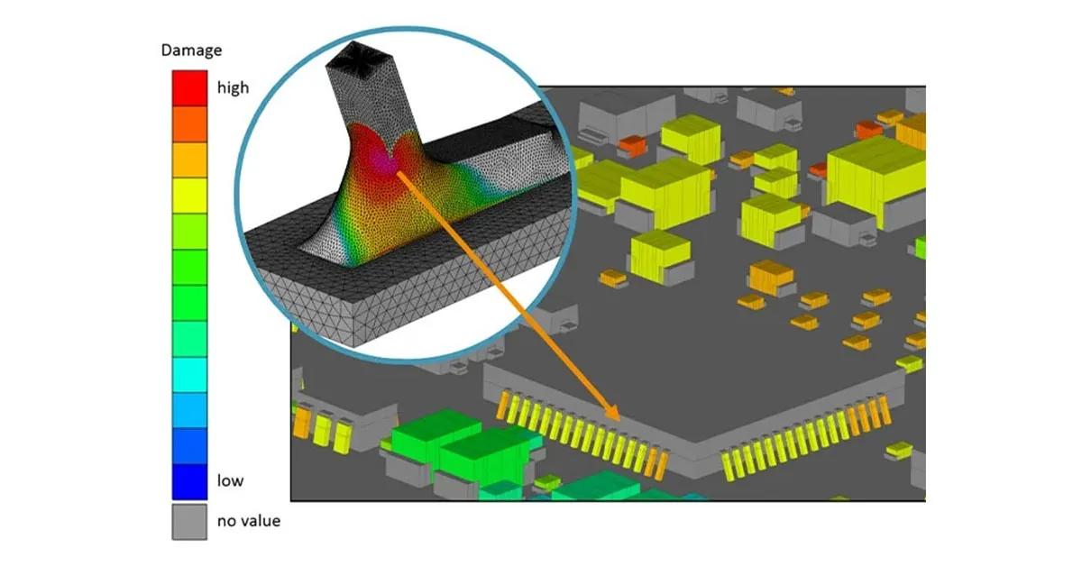
Finite element analysis (FEA) for solder fatigue is a simulation technique that models the behavior of solder joints under stress. Using PCB design software like ANSYS or Abaqus, engineers create a digital model of the solder joint and apply simulated thermal or mechanical loads. FEA can predict stress distribution, strain, and potential failure points with high accuracy.
For instance, in a thermal cycling simulation, FEA might reveal that a solder joint experiences a peak stress of 50 MPa at the corner of a ball grid array (BGA) package during a temperature shift from -40°C to 125°C. By analyzing these results, you can estimate the number of cycles to failure using fatigue models like the Coffin-Manson equation, which relates plastic strain to fatigue life. A typical result might show a lifespan of 2,500 cycles under these conditions.
FEA is invaluable because it allows you to test designs virtually before physical prototyping, saving time and PCB manufacturing cost. However, it requires expertise in material properties and accurate input data, such as the solder’s creep behavior and elastic modulus (e.g., 40 GPa for SAC305 solder alloy).
Empirical Models and Accelerated Life Testing
Besides FEA, empirical models like the Engelmaier model are widely used for solder joint fatigue life prediction. These models use experimental data to correlate stress conditions with fatigue life. For example, the Engelmaier model accounts for shear strain in solder joints during thermal cycling and can predict failure after a specific number of cycles based on temperature range and dwell time.
Accelerated life testing (ALT) complements these models by subjecting solder joints to harsher conditions (e.g., rapid temperature changes from -55°C to 125°C every 30 minutes) to speed up failure. Results are then extrapolated to normal operating conditions using equations like the Arrhenius model, which adjusts for temperature effects on reaction rates. ALT can reduce testing time from months to weeks, making it practical for product development.
Solder Joint Fatigue Testing: Practical Approaches
While simulations are powerful, physical testing remains essential to validate predictions. Solder joint fatigue testing involves subjecting assemblies to controlled stress conditions and monitoring for failure. Here are two common testing methods:
Thermal Cycling Tests
Thermal cycling tests replicate real-world temperature fluctuations. A test chamber cycles the temperature between extremes (e.g., -40°C to 125°C) while monitoring the solder joints for cracks or electrical failures. Standards like IPC-9701 define test profiles, often specifying 1,000 cycles as a benchmark for reliability. During testing, engineers might use microscopes or X-ray imaging to detect micro-cracks as small as 10 micrometers, indicating early fatigue.
Suggested Reading:BGA X-Ray Secrets: Detecting Hidden Solder Joint Issues for Enhanced Performance
Vibration Testing
For vibration fatigue in solder joints, vibration testing applies mechanical stress using shaker tables. Tests follow standards like MIL-STD-810, simulating frequencies and amplitudes relevant to the application (e.g., 20-2,000 Hz for automotive components). Failure is often detected through electrical continuity checks, as cracks can interrupt signal paths.
Both thermal and vibration testing provide real-world data to refine FEA models and empirical predictions, ensuring your designs are robust.
Strategies to Prevent Solder Joint Fatigue Failures
Now that we’ve covered prediction and testing, let’s focus on prevention. Here are actionable strategies to enhance solder joint reliability:
Material Selection
Choosing the right solder alloy is critical. Lead-free solders like SAC305 (Sn-3.0Ag-0.5Cu) are common due to environmental regulations, but they are more prone to fatigue than traditional lead-based solders. SAC305 has a fatigue life of about 2,000 cycles under standard thermal conditions, compared to 3,000 for SnPb solder. Consider alloys with additives like bismuth or indium for improved performance in high-stress applications.
Design Optimization
Design plays a huge role in fatigue prevention. Minimize CTE mismatches by matching the thermal expansion of components and PCBs (e.g., using FR-4 boards with a CTE of 14-17 ppm/°C for common IC packages). Additionally, avoid placing large components near board edges where vibration stress is higher. Adding underfill materials can also reduce strain on BGA solder joints by up to 50%, extending lifespan.
Manufacturing Quality
Poor soldering techniques can introduce defects like voids, which act as stress concentrators. Use vacuum reflow soldering to minimize voiding (targeting less than 10% void area per joint) and ensure proper flux application to avoid weak bonds. Post-assembly inspection using X-ray or acoustic microscopy can catch defects early.
Suggested Reading:Improving Solder Joint Quality in PCB Wave Soldering: A Step-by-Step Approach
Real-World Applications and Case Studies
Let’s look at how these principles apply in practice. In the automotive industry, electronic control units (ECUs) face both thermal cycling fatigue in solder and vibration fatigue in solder joints. A study by a major automaker found that using SAC305 solder with underfill increased fatigue life by 40% under combined thermal (-40°C to 105°C) and vibration (50 Hz) testing. This improvement reduced warranty claims significantly.
In aerospace, where reliability is non-negotiable, engineers rely heavily on finite element analysis for solder fatigue to simulate conditions like rapid temperature changes during flight (e.g., from 25°C to -55°C in minutes). Coupling FEA with solder joint fatigue testing ensures mission-critical systems don’t fail mid-operation.
Challenges and Future Trends in Solder Joint Fatigue Analysis
Despite advances, challenges remain in solder joint fatigue analysis. Miniaturization of electronics means smaller joints with less material to absorb stress, reducing fatigue life. Additionally, new materials like high-temperature solders for 5G applications require updated fatigue models, as current data is limited.
Looking ahead, machine learning is emerging as a tool for solder joint fatigue life prediction. By training algorithms on vast datasets from FEA and testing, engineers can predict failures with greater accuracy. Industry reports suggest AI-driven models could reduce prediction errors by 20% within the next five years.
Conclusion: Taking Control of Solder Joint Reliability
Solder joint fatigue is a complex challenge, but with the right tools and strategies, electrical engineers can predict lifespan and prevent failures effectively. By leveraging finite element analysis for solder fatigue, conducting thorough solder joint fatigue testing, and optimizing design and materials, you can tackle issues like thermal cycling fatigue in solder and vibration fatigue in solder joints. Start by integrating these practices into your workflow—whether it’s running an FEA simulation or refining your thermal cycling test protocols—and watch your designs become more reliable.


