 ALLPCB


In the world of electronics, high-power applications require circuit boards that can handle intense electrical loads, extreme heat, and demanding conditions. So, why do these applications often rely on aluminum PCBs? Simply put, aluminum PCBs offer superior thermal performance, high current carrying capacity, and robust design, making them ideal for managing the challenges of high-power systems. In this blog, we’ll dive deep into the reasons behind their popularity, exploring key aspects like thermal management, electrical capabilities, and durability for high-power aluminum PCB design.
What Are Aluminum PCBs and Why Do They Matter?
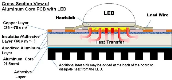
Aluminum PCBs, also known as metal core PCBs (MCPCBs), are a type of printed circuit board that uses a metal base, typically aluminum, instead of the traditional FR4 material. This metal layer acts as a heat sink, efficiently dissipating heat away from critical components. For high-power applications such as LED lighting, power supplies, automotive electronics, and industrial equipment, managing heat is crucial to prevent damage and ensure reliability.
Unlike standard PCBs, aluminum PCBs are built to withstand higher temperatures and electrical loads. Their unique construction includes a thermally conductive dielectric layer between the aluminum base and the copper circuit layer, balancing electrical insulation with heat transfer. This makes them a go-to choice for engineers working on systems where thermal performance aluminum PCB design is a top priority.
Thermal Performance: The Heart of Aluminum PCB Design
One of the standout features of aluminum PCBs is their exceptional thermal performance. High-power applications generate significant heat, which can degrade components, reduce lifespan, and cause system failures if not managed properly. Aluminum, with its high thermal conductivity of approximately 200 W/m·K (compared to FR4’s 0.3 W/m·K), excels at pulling heat away from hot spots and distributing it across the board.
For instance, in LED lighting systems, where power densities can exceed 10 W/in2, aluminum PCBs prevent overheating by transferring heat to a larger surface area or an external heat sink. This capability ensures that components operate within safe temperature ranges, often below 85°C, even under continuous high-power operation. By maintaining lower junction temperatures, thermal performance aluminum PCB designs enhance efficiency and reliability in demanding environments.
Moreover, the reduced thermal resistance in aluminum PCBs—often as low as 1-2°C/W compared to 5-10°C/W in standard boards—means less energy is wasted as heat, improving overall system performance. This is especially critical in power electronics, where every degree of temperature reduction can extend operational life by thousands of hours.

Aluminum PCB Current Carrying Capacity: Handling High Loads
High-power applications often involve substantial electrical currents, and the aluminum PCB current carrying capacity is a key reason they’re chosen over traditional boards. The copper traces on PCBs are responsible for conducting current, but in high-power scenarios, narrow or thin traces can overheat due to resistance, leading to voltage drops or even trace burnout.
Aluminum PCBs are typically designed with thicker copper layers, ranging from 2 oz/ft2 to 10 oz/ft2, compared to the standard 1 oz/ft2 on many FR4 boards. This increased thickness allows them to carry currents upwards of 30-50 amps on wider traces (e.g., 100 mils or more) without significant temperature rise. For comparison, a 1 oz/ft2 copper trace might handle only 5-10 amps before exceeding safe temperature limits of around 30°C above ambient.
The metal core also aids in heat dissipation during high-current operation, preventing localized hot spots that could damage the board. This makes aluminum PCBs ideal for applications like motor controllers or power converters, where current spikes are common. Engineers can design layouts with optimized trace widths and spacing to maximize aluminum PCB current carrying capacity while minimizing resistance losses, often keeping voltage drops below 0.1V across critical paths.
Aluminum PCB Voltage Rating: Built for High-Voltage Systems
In addition to handling high currents, aluminum PCBs are well-suited for high-voltage applications due to their robust dielectric layers. The aluminum PCB voltage rating depends on the insulating material between the metal core and the copper layer, which is designed to prevent electrical breakdown under high potential differences.
Typical aluminum PCB can support voltage ratings from 500V to over 2000V, depending on the thickness and quality of the dielectric layer. For example, a dielectric layer with a breakdown voltage of 3 kV/mm and a thickness of 0.1 mm can safely insulate up to 300V. This makes them suitable for power supply units, inverters, and renewable energy systems where voltages can reach 600V or more.
The ability to maintain electrical isolation while managing heat is a critical advantage. In high-voltage designs, engineers must also consider creepage and clearance distances—gaps between conductive elements—to prevent arcing. Aluminum PCBs often provide better spacing options due to their larger surface area for heat dissipation, allowing for safer high-voltage layouts. This focus on aluminum PCB voltage rating ensures that high-power systems remain safe and reliable even under extreme electrical stress.
Robust PCB Design: Durability for Demanding Environments
High-power applications often operate in harsh conditions, from industrial factories with vibrations to automotive systems exposed to temperature swings. Robust PCB design is essential to ensure longevity and performance, and aluminum PCBs deliver on this front with their mechanical strength and environmental resistance.
The aluminum base provides a sturdy foundation, reducing the risk of cracking or warping under mechanical stress. This is a significant improvement over FR4 boards, which can delaminate or fracture when subjected to repeated thermal cycling or physical shocks. Aluminum PCBs can endure temperature ranges from -40°C to 150°C without losing structural integrity, making them ideal for outdoor or rugged applications.
Additionally, the metal core offers better resistance to moisture and corrosion when properly coated, ensuring reliability in humid or chemically aggressive environments. For example, in automotive electronics, where boards are exposed to road vibrations and temperature fluctuations, robust PCB design with aluminum cores can achieve operational lifespans exceeding 100,000 hours. This durability translates to lower maintenance costs and fewer system failures, a critical factor for engineers designing for reliability.
Key Design Considerations for High-Power Aluminum PCBs
While aluminum PCBs offer numerous advantages, achieving optimal performance in high-power applications requires careful design. Here are some practical tips for engineers focusing on high power aluminum PCB design:
- Material Selection: Choose a dielectric material with high thermal conductivity (e.g., 1-3 W/m·K) and appropriate breakdown voltage to balance heat transfer and insulation. Thicker aluminum bases (1.6 mm or more) can enhance heat spreading for extreme power loads.
Suggested Reading: How to Choose the Best Dielectric Material for Aluminum PCBs
- Trace Layout: Use wider and thicker copper traces to handle high currents, and minimize trace length to reduce resistance and heat buildup. For instance, a 5 oz/ft2 trace at 200 mils wide can carry over 40 amps with minimal temperature rise.
- Heat Sink Integration: Design the PCB to interface directly with external heat sinks or enclosures, leveraging the aluminum core to transfer heat efficiently. Ensure thermal vias are placed near heat-generating components to enhance dissipation.
- Component Placement: Position high-power components like MOSFETs or IGBTs near the aluminum core for direct heat transfer, and avoid clustering heat sources to prevent thermal overlap.
- Testing and Simulation: Use thermal simulation tools to predict temperature profiles and identify potential hot spots before fabrication. Validate designs with real-world testing under maximum load conditions to confirm performance.
By focusing on these elements, engineers can maximize the benefits of aluminum PCBs, ensuring both safety and efficiency in high-power systems.
Applications of Aluminum PCBs in High-Power Systems
Aluminum PCBs are widely used across industries where high power and heat management are critical. Some common applications include:
- LED Lighting: High-power LEDs, often operating at 10-50W, rely on aluminum PCBs to manage heat and maintain brightness over time. This is evident in streetlights and industrial lighting solutions.
- Power Electronics: Converters, inverters, and power supplies handling hundreds of watts benefit from the thermal and electrical capabilities of aluminum PCBs, ensuring stable operation.
Suggested Reading: Boosting Performance: The Role of Aluminum PCBs in Power Electronics
- Automotive Systems: Electric vehicle battery management systems and motor controllers use aluminum PCBs for their ability to handle high currents (up to 100A) and resist harsh conditions.
Suggested Reading: Solving Heat Issues: How Aluminum PCBs Enhance Automotive Electronics
- Industrial Equipment: Machinery with high-voltage circuits and significant power demands depends on robust PCB design to prevent failures in demanding environments.
These examples highlight how aluminum PCBs meet the unique needs of high-power applications, providing a reliable foundation for cutting-edge technology.
Conclusion: The Future of High-Power Design with Aluminum PCBs
High-power applications demand solutions that can handle intense electrical loads, extreme heat, and challenging environments. Aluminum PCBs rise to this challenge with their unmatched thermal performance, high current carrying capacity, impressive voltage ratings, and robust design. Whether it’s for LED lighting, power electronics, or automotive systems, high power aluminum PCB design offers engineers a reliable way to push the boundaries of performance and efficiency.
By understanding the strengths of thermal performance aluminum PCB layouts, optimizing aluminum PCB current carrying capacity, ensuring safe aluminum PCB voltage ratings, and prioritizing robust PCB design, you can create systems that excel under the toughest conditions. As technology continues to evolve, aluminum PCBs will remain a cornerstone of innovation, driving the future of high-power electronics with strength and precision.


