 ALLPCB


In the world of electronics, managing heat in a 6-layer PCB is critical for ensuring performance, reliability, and longevity. As components become more powerful and densely packed, heat dissipation becomes a major challenge. So, how do you keep your 6-layer PCB cool? The answer lies in strategic design techniques like using thermal vias, optimizing component placement, selecting the right materials, and leveraging thermal simulation tools. In this comprehensive guide, we’ll dive deep into effective thermal management strategies for 6-layer PCBs, covering everything from heat dissipation techniques to material selection for thermal performance. Let’s explore how to keep your boards running cool and efficient.
Why Thermal Management Matters in 6-Layer PCBs
A 6-layer PCB, with its multiple layers of conductive copper and insulating material, is often used in complex, high-performance applications like telecommunications, automotive systems, and industrial controls. These boards handle high power densities and fast signal speeds, which generate significant heat. If not managed properly, excessive heat can lead to component failure, reduced lifespan, and unreliable performance. Effective PCB thermal management ensures that heat is dissipated efficiently, maintaining optimal operating temperatures—typically below 85°C for most components, though specific thresholds depend on the parts used.
Beyond protecting components, good thermal design also improves signal integrity and prevents thermal stress on the board itself. In this guide, we’ll break down proven techniques to address these challenges, focusing on practical solutions for engineers working with 6-layer designs.
Understanding Heat Sources in 6-Layer PCBs
Before diving into solutions, it’s important to identify where heat comes from in a 6-layer PCB. The primary sources include:
- Power Components: High-power components like voltage regulators, processors, and power amplifiers generate significant heat, often exceeding 5-10 watts per component in demanding applications.
- High-Speed Signals: Fast-switching signals in digital circuits create heat due to resistive losses in copper traces.
- Dense Layouts: Compact designs with closely packed components limit airflow and trap heat, especially in inner layers where natural convection is minimal.
With the multiple layer, heat can become trapped between copper planes, making dissipation more complex than in the simpler 2- or 4 layer PCB. Let’s look at targeted strategies to tackle these issues.
6-Layer PCB Heat Dissipation Techniques
Effective heat dissipation is the foundation of thermal management. Here are some key techniques tailored for 6-layer PCBs:
1. Use of Copper Planes for Heat Spreading
In a 6-layer PCB, dedicating one or more internal layers as a ground or power plane can significantly improve heat distribution. Copper has a thermal conductivity of about 400 W/m·K, making it an excellent material for spreading heat across the board. Thicker copper layers, such as 2 oz (70 μm) instead of the standard 1 oz (35 μm), can enhance this effect by providing a larger thermal mass to absorb and dissipate heat.
Tip: Connect heat-generating components directly to these planes using thermal pads or vias to create a low-resistance path for heat to spread.
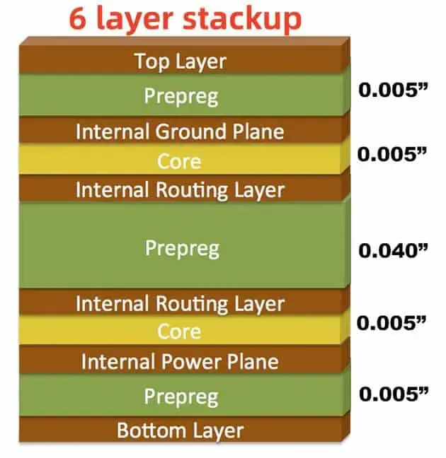
2. Strategic Layer Stackup Design
The arrangement of layers in a 6-layer PCB impacts thermal performance. Place power and ground planes closer to the surface layers to facilitate heat transfer to external heat sinks or the ambient environment. A common stackup might be:
- Layer 1: Signal (Top)
- Layer 2: Ground Plane
- Layer 3: Signal
- Layer 4: Signal
- Layer 5: Power Plane
- Layer 6: Signal (Bottom)
This configuration ensures that heat from components on the top and bottom layers can easily reach the planes for dissipation.
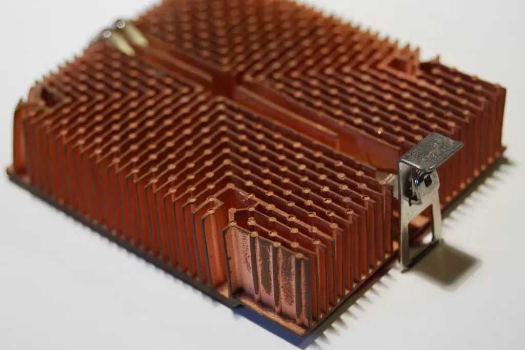
3. External Heat Sinks and Cooling Solutions
For high-power components, attaching external heat sinks can be a game-changer. Heat sinks increase the surface area available for heat dissipation, often reducing component temperatures by 20-30°C. Ensure a good thermal interface material (TIM) like thermal paste or pads is used between the component and heat sink to minimize thermal resistance, which can be as low as 0.5°C/W with high-quality materials.
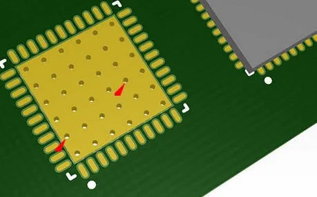
6-Layer PCB Thermal Vias: A Key to Heat Transfer
Thermal vias are small, plated-through holes that conduct heat from one layer of the PCB to another, often connecting surface-mounted components to internal copper planes or the opposite side of the board. In a 6-layer PCB, thermal vias are especially important because heat can get trapped in inner layers.
How to Design Thermal Vias
For optimal performance, use multiple small vias (e.g., 0.3 mm diameter) rather than a few large ones. A grid of 5-10 vias under a high-power component can reduce thermal resistance by up to 50% compared to a single via. Space them evenly, with a pitch of about 1.2-1.5 mm, to maximize heat distribution without compromising structural integrity.
Fill the vias with conductive epoxy or plug them to prevent solder wicking during assembly, which can create air gaps and reduce thermal conductivity. Studies suggest that filled vias can improve heat transfer by 10-15% compared to unfilled ones.
Placement Tips
Place thermal vias directly beneath or near heat-generating components like ICs or power transistors. Connect them to large copper areas on internal planes to spread heat effectively across the board.
6-Layer PCB Component Placement for Thermal Management
Where you place components on a 6-layer PCB can make a big difference in how heat is managed. Poor placement can create hotspots, while strategic placement ensures even heat distribution.
Key Guidelines for Component Placement
- Space Out Heat Sources: Avoid clustering high-power components together. Spread them across the board to prevent localized heating. For example, if two components each dissipate 5 watts, placing them 20 mm apart can reduce peak temperatures by 10-15°C compared to a 5 mm separation.
- Position Near Edges: Place heat-generating parts near the board’s edges or areas with better airflow to allow natural convection to carry heat away.
- Prioritize Sensitive Components: Keep temperature-sensitive components, like precision analog ICs, away from heat sources to maintain their performance within specified ranges (often 0-70°C for commercial-grade parts).
By planning your layout with thermal considerations in mind, you can minimize the risk of overheating and improve overall board reliability.
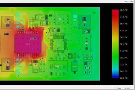
6-Layer PCB Thermal Simulation: Predicting and Preventing Issues
Thermal simulation is a powerful tool for identifying potential heat problems before manufacturing a 6-layer PCB. Using PCB software tools, engineers can model heat flow, identify hotspots, and test different design configurations virtually.
Benefits of Thermal Simulation
Simulation allows you to predict temperatures across the board under various operating conditions. For instance, you can simulate a power dissipation of 10 watts from a processor and see if the junction temperature stays below the safe limit of 125°C. This data helps you adjust via placement, copper thickness, or component positioning early in the design phase, saving time and cost.
How to Perform Thermal Simulation
Start by inputting accurate data into your simulation tool, including:
- Power dissipation values for each component (e.g., 2.5 W for a specific IC).
- Thermal conductivity of materials (e.g., 0.3 W/m·K for standard FR-4).
- Ambient temperature and airflow conditions (e.g., 25°C with no forced cooling).
Run the simulation to generate a thermal map of the board. Look for areas exceeding safe temperature thresholds and adjust the design accordingly, such as adding more vias or repositioning components.
6-Layer PCB Material Selection for Thermal Performance
The materials used in a 6-layer PCB play a huge role in how well it handles heat. Choosing the right substrate and copper thickness can significantly improve thermal performance.
Substrate Materials
Standard FR-4, with a thermal conductivity of about 0.3 W/m·K, works for low to moderate heat applications. However, for high-power designs, consider advanced materials like:
- High-Tg FR-4: Offers better thermal stability, withstanding temperatures up to 170°C compared to 130°C for standard FR-4.
- Polyimide: With a thermal conductivity of 0.5 W/m·K, it’s ideal for high-temperature environments.
- Metal-Core PCBs (MCPCB): These use a metal base layer (often aluminum) with thermal conductivity up to 1-2 W/m·K, drastically improving heat dissipation.
Suggested Reading: 6-Layer PCB Materials Guide: Choosing the Right Substrate for Your Application
Copper Thickness
When it comes to PCB copper thickness, thicker copper layers improve heat spreading. For power-intensive 6-layer PCBs, opt for 2 oz or even 3 oz copper on power and ground planes. This can reduce thermal resistance by 20-30% compared to 1 oz copper, though it increases manufacturing costs.
Dielectric Thickness
Thinner dielectric layers between copper planes allow heat to transfer more easily to inner layers or the opposite side of the board. A dielectric thickness of 0.1 mm, for example, offers better thermal performance than 0.2 mm, though it may affect signal integrity and must be balanced with electrical requirements.
Additional Tips for 6-Layer PCB Thermal Management
Beyond the core strategies, here are a few extra tips to enhance thermal performance:
- Use Thermal Pads: Place thermal pads under components to improve heat transfer to the PCB. Ensure proper soldering to avoid air gaps, which can increase thermal resistance by up to 1°C/W per gap.
- Optimize Airflow: If the PCB is housed in an enclosure, design vents or use fans to promote airflow, reducing ambient temperatures around the board by 5-10°C.
- Monitor Temperatures: During testing, use thermal cameras or sensors to measure actual temperatures on the board. Compare these with simulation results to refine your design.
Conclusion: Building Cooler, More Reliable 6-Layer PCBs
Thermal management in 6-layer PCBs is a multifaceted challenge that requires careful planning and execution. By leveraging techniques like thermal vias, strategic component placement, and advanced materials, you can effectively manage heat dissipation and keep your boards cool. Tools like thermal simulation further empower you to predict and prevent issues before they arise, ensuring reliability in high-performance applications.
At ALLPCB, we understand the importance of thermal management in complex designs. Whether you’re optimizing heat dissipation with vias or selecting materials for peak thermal performance, these strategies will help you create robust, long-lasting 6-layer PCBs. Start applying these techniques in your next project to achieve better results and maintain optimal operating conditions for your electronics.


