 ALLPCB


In the fast-growing world of wearable technology, fitness trackers have become essential tools for health-conscious individuals. However, one of the biggest challenges for these devices is battery life. How can you design a fitness tracker PCB that minimizes power consumption while maintaining performance? The answer lies in low power PCB design techniques, efficient power management ICs, and optimizing components like BLE for reduced energy use. In this blog, we’ll dive deep into strategies for extending fitness tracker battery life through energy-efficient PCB design.
Why Power Consumption Matters in Fitness Trackers
Fitness trackers are small, wearable devices that monitor steps, heart rate, sleep patterns, and more. Since they’re powered by tiny batteries, every milliwatt of energy counts. Users expect these devices to last days or even weeks on a single charge, making low power PCB design a critical factor in their success. High power consumption not only shortens battery life but also increases heat generation, which can affect user comfort and device reliability.
By focusing on energy-efficient PCB layouts, selecting the right power management IC, and minimizing BLE power consumption, designers can create fitness trackers that balance performance with long-lasting battery life. Let’s explore actionable strategies to achieve this.
Key Strategies for Low Power PCB Design in Fitness Trackers
Designing a PCB for minimal power consumption requires a combination of smart component choices, optimized layouts, and advanced techniques. Below are some proven methods to achieve energy efficiency in fitness tracker designs.
1. Choose Low-Power Components
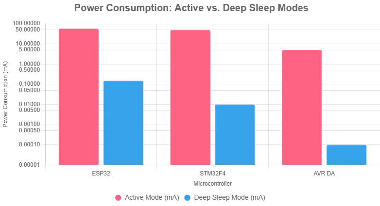
The foundation of an energy-efficient PCB starts with selecting components that inherently consume less power. For fitness trackers, this means using microcontrollers (MCUs) and sensors with low quiescent current—often in the range of microamps (μA) during idle modes. For example, many modern MCUs offer sleep modes where power draw drops below 1 μA, compared to active mode consumption of several milliamps (mA).
Additionally, opt for sensors with built-in power-saving features. Heart rate sensors, for instance, can be programmed to take readings at intervals (e.g., every 10 seconds) rather than continuously, reducing power usage by up to 50% in some cases. Always review datasheets to compare power profiles before finalizing components.
2. Implement Efficient Power Management ICs
A power management IC (PMIC) is the heart of energy efficiency in any fitness tracker. These chips regulate voltage, manage battery charging, and control power distribution to various components. A well-chosen PMIC can reduce power loss during voltage conversion, often achieving efficiencies above 90% compared to less optimized solutions that might hover around 70-80%.
Look for PMICs with features like dynamic voltage scaling, which adjusts voltage levels based on the device’s workload. For instance, during low-activity periods, the PMIC can lower the supply voltage to the MCU, cutting power draw by 20-30%. Also, ensure the PMIC supports ultra-low quiescent current in standby mode—some advanced chips consume as little as 0.5 μA when idle.
Integrating a PMIC with multiple output rails can further optimize power by providing tailored voltage levels to different components, avoiding unnecessary energy waste. This targeted approach is especially useful in fitness trackers with diverse power needs for displays, sensors, and wireless modules.
3. Optimize BLE Power Consumption
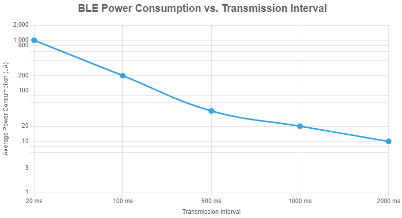
Bluetooth Low Energy (BLE) is the go-to wireless technology for fitness trackers due to its low power profile compared to classic Bluetooth. However, BLE power consumption can still be a significant drain if not managed properly. During active transmission, BLE modules can draw 10-15 mA, but in sleep mode, this can drop to under 1 μA.
To minimize BLE power usage, reduce the frequency and duration of data transmissions. For example, instead of syncing data every minute, configure the tracker to sync every 5 minutes or only when the user initiates a connection via a smartphone app. Additionally, use the lowest possible transmission power level that still ensures a reliable connection—reducing output power from +4 dBm to 0 dBm can cut current draw by nearly 30% in some setups.
Another tip is to leverage BLE’s advertising mode efficiently. By shortening advertising intervals during inactive periods, you can save power without sacrificing connectivity. Modern BLE chips also offer deep sleep modes, so ensure your design takes full advantage of these features.
Advanced Techniques for Energy-Efficient PCB Layouts
Beyond component selection, the physical layout of the PCB plays a huge role in power efficiency. A poorly designed layout can introduce parasitic effects that increase power loss, while a well-thought-out design minimizes these issues.
4. Minimize Trace Lengths and Resistance
Long traces on a PCB create higher resistance, leading to power loss as heat. For fitness trackers, where space is already tight, aim to keep power traces as short and wide as possible. A typical trace width of 10-15 mils for power lines can handle currents up to 1 A with minimal voltage drop, compared to narrower traces that might lose 5-10 mV over a short distance.
Place high-current components, like the PMIC and battery connector, close to each other to reduce trace length. Use copper pours for ground planes to lower impedance and improve heat dissipation, which indirectly aids in maintaining power efficiency by preventing thermal throttling.
5. Use Multi-Layer PCBs for Better Power Distribution
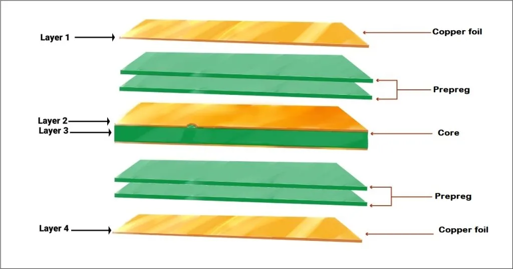
While single-layer PCBs are cheaper, they’re often insufficient for complex fitness tracker designs. Multi-layer PCBs (typically 4 layers) allow for dedicated power and ground planes, reducing noise and improving power delivery. This setup can decrease power loss by up to 15% compared to single-layer designs with shared ground traces.
In a 4-layer stackup, allocate one layer for power distribution and another for ground. This separation minimizes crosstalk and ensures stable voltage delivery to components, which is crucial for maintaining low power operation in sensitive circuits like analog sensors.
6. Incorporate Power Gating Techniques
Power gating is a technique where unused sections of the PCB are turned off to save energy. In a fitness tracker, not all components need to be active at once. For example, the display can be powered down when not in use, and sensors can be disabled during idle periods.
Implement power gating by using low-leakage transistors or dedicated switches controlled by the MCU. This can reduce static power consumption by up to 90% in inactive circuits. However, be mindful of wake-up latency—ensure the system can quickly reactivate components without noticeable delays to the user.
Software Optimization for Fitness Tracker Battery Life
While hardware design is critical, software plays an equally important role in managing power consumption. Firmware can control when and how components operate, directly impacting battery life.
7. Leverage Sleep and Deep Sleep Modes
Most MCUs and sensors in fitness trackers support multiple power modes, from active to deep sleep. In deep sleep, power draw can be as low as 0.1 μA, compared to 1-2 mA in active mode. Program the firmware to enter deep sleep during periods of inactivity, such as when the user is asleep or the device hasn’t detected motion for a set time (e.g., 5 minutes).
Use interrupts to wake the system only when necessary, such as for a button press or scheduled sensor reading. This approach can extend fitness tracker battery life by hours or even days, depending on usage patterns.
8. Optimize Data Processing and Storage
Processing and storing data consumes power, especially if done inefficiently. Avoid continuous data logging—instead, batch sensor readings and process them in short bursts. For example, store heart rate data every 30 seconds rather than every second, reducing MCU active time by up to 95%.
Also, minimize the use of external memory writes, as flash storage operations can draw significant current (often 5-10 mA per write). Compress data before storage to reduce write frequency and save energy.
Testing and Validation for Power Efficiency
Once your PCB design and firmware are in place, thorough testing is essential to ensure power optimization. Use a precision multimeter or power analyzer to measure current draw in various operating modes. For instance, verify that sleep mode current is below 1 μA and active mode peaks align with expected values (e.g., 10-20 mA during BLE transmission).
Simulate real-world usage scenarios, such as continuous heart rate monitoring or periodic syncing, to identify power bottlenecks. If a specific component exceeds expected power draw, revisit its configuration or consider a replacement with a more efficient alternative.
Challenges in Low Power PCB Design for Fitness Trackers
While the strategies above can significantly improve energy efficiency, there are challenges to consider. Balancing power savings with performance is a constant trade-off—reducing sensor sampling rates might save power but could compromise data accuracy. Similarly, minimizing BLE transmission power may lead to connection issues in noisy environments.
Space constraints also pose a challenge. Fitness trackers demand compact PCBs, often less than 30 mm x 30 mm, making it difficult to implement wide traces or extensive power planes. Careful planning and iterative design are necessary to overcome these limitations without sacrificing efficiency.
Future Trends in Energy-Efficient PCB Design for Wearables
The field of wearable technology is evolving rapidly, and so are the techniques for power optimization. Emerging trends include the use of energy harvesting, where ambient energy from motion or heat is converted into usable power, potentially reducing reliance on batteries. Some prototypes have demonstrated harvesting up to 50 μW from wrist movements—enough to power low-energy sensors.
Additionally, advancements in semiconductor technology are leading to even lower power components. Next-generation MCUs and PMICs are being designed with sub-0.1 μA sleep currents, promising significant improvements in fitness tracker battery life over the coming years.
Conclusion: Powering the Future of Fitness Trackers
Optimizing power consumption in fitness tracker PCBs is a multifaceted challenge that requires careful attention to component selection, PCB layout, and firmware design. By implementing low power PCB design techniques, leveraging efficient power management ICs, and minimizing BLE power consumption, you can create energy-efficient PCBs that extend battery life without compromising functionality.
From choosing components with ultra-low quiescent currents to employing power gating and sleep modes, every decision in the design process impacts the final product’s efficiency. As technology continues to advance, staying informed about new tools and techniques will be key to designing the next generation of long-lasting fitness trackers.
At ALLPCB, we’re committed to supporting engineers and designers in creating innovative, energy-efficient solutions for wearable devices. Whether you’re prototyping a new fitness tracker or refining an existing design, our expertise in PCB manufacturing can help bring your vision to life with precision and reliability.


