ALLPCB


Are you struggling with electromagnetic interference (EMI) in your wind turbine control systems? For electrical engineers working on these critical systems, minimizing EMI is essential for ensuring reliable operation, achieving EMC compliance, and maintaining signal integrity. In this blog, we’ll explore proven PCB layout techniques for EMI reduction, focusing on grounding techniques, signal integrity, and wind turbine PCB layout best practices. Let’s dive into actionable strategies to help you design robust control systems for wind turbines.
Why EMI Matters in Wind Turbine Control Systems
Wind turbine control systems are at the heart of efficient energy generation. These systems manage everything from blade pitch to power output, often operating in harsh environments with high levels of electromagnetic noise. EMI can disrupt sensitive electronics, leading to signal errors, system malfunctions, or even complete failures. For instance, interference from high-power inverters or nearby lightning strikes can couple into control circuits, causing data corruption or unexpected shutdowns.
Ensuring EMC (electromagnetic compatibility) compliance is not just about passing regulatory tests; it’s about guaranteeing safety and reliability in real-world conditions. Poor EMI management can result in costly downtime or maintenance issues. That’s why adopting effective PCB layout techniques for EMI reduction is critical for engineers designing wind turbine control systems.

Key Challenges of EMI in Wind Turbine PCB Design
Before diving into solutions, let’s understand the unique EMI challenges in wind turbine control systems:
- High-Power Components: Wind turbines use high-voltage inverters and converters that generate significant electromagnetic noise, often in the range of 50 kHz to 1 MHz, which can couple into nearby control circuits.
- Harsh Environments: Turbines are exposed to lightning strikes, temperature extremes, and vibration, increasing the risk of EMI-induced failures.
- Long Cable Runs: Control signals often travel through long cables, acting as antennas for radiated EMI.
- Compact Designs: Space constraints in turbine nacelles force dense PCB layouts, making it harder to separate noisy and sensitive circuits.
Addressing these challenges requires a strategic approach to PCB layout, focusing on grounding, shielding, and signal routing. Let’s explore specific techniques for minimizing EMI.
Essential PCB Layout Techniques for EMI Reduction
1. Implement Robust Grounding Techniques
Grounding is the foundation of EMI reduction in any PCB design, especially for wind turbine control systems. A well-designed ground plane minimizes noise by providing a low-impedance path for return currents, reducing the loop area where EMI can couple.
Key Grounding Tips:
- Use a Solid Ground Plane: Avoid split ground planes unless absolutely necessary. A continuous ground plane under signal traces reduces impedance and prevents return currents from taking unintended paths. Aim for a ground plane resistance of less than 1 ohm for critical systems, as suggested by industry standards for high-reliability applications.
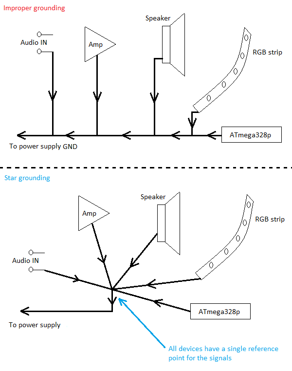
- Separate Analog and Digital Grounds: In mixed-signal designs, keep analog and digital grounds separate and connect them at a single point near the power supply to prevent digital noise from contaminating sensitive analog signals.
- Ground Stitching Vias: Place vias around the PCB edges to connect multiple ground layers, creating a Faraday cage-like effect to block radiated EMI. Space vias at intervals of λ/20 (where λ is the wavelength of the highest frequency signal, e.g., 15 mm for a 1 GHz signal) to ensure effective shielding.

2. Optimize Signal Integrity Through Trace Routing
Signal integrity is crucial for preventing EMI in high-speed control circuits. Poor trace routing can create impedance mismatches, reflections, and crosstalk, all of which amplify EMI risks.
Trace Routing Best Practices:
- Minimize Trace Lengths: Keep high-speed signal traces as short as possible to reduce the loop area for EMI coupling. For example, a 10 cm trace can act as an antenna for frequencies around 750 MHz.
- Avoid Routing Near Board Edges: Traces near PCB edges are more susceptible to radiated EMI. Maintain a clearance of at least 5 mm from the edge to minimize interference.
- Use Differential Pairs: For critical signals like CAN bus or RS-485 used in turbine control, route them as differential pairs with matched lengths to cancel out common-mode noise. Maintain a trace separation of 2-3 times the trace width for optimal performance.
- Avoid Stubs: Stub traces can resonate at specific frequencies, acting as unintentional antennas. Terminate unused traces or keep them under 1/10th of the signal wavelength.
By prioritizing signal integrity in your wind turbine PCB layout, you can significantly reduce EMI-related signal corruption.
3. Strategic Component Placement for EMI Control
Where you place components on a PCB can make or break your EMI performance. Grouping and isolating components based on their noise profiles is a proven technique.
Component Placement Tips:
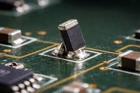
- Isolate Noisy Components: Place high-noise components like switching regulators or power inverters away from sensitive analog circuits such as sensors or ADCs. A separation of at least 20 mm can help reduce coupling.
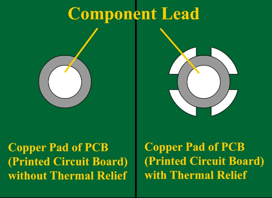
- Use Decoupling Capacitors: Position decoupling capacitors (e.g., 0.1 μF ceramic capacitors) as close as possible to the power pins of ICs to suppress high-frequency noise. Ensure the loop between the capacitor and IC is less than 5 mm for maximum effectiveness.
- Shield Sensitive Areas: Use metal shields or guard rings around sensitive components like microcontrollers to block radiated EMI. Ground the shield directly to the ground plane with multiple vias.

4. Power Distribution Network (PDN) Design for EMC Compliance
A poorly designed power distribution network can act as a source of EMI, radiating noise across the PCB. For wind turbine control systems, where power demands fluctuate, a stable PDN is essential.
PDN Design Strategies:
- Low-Impedance Power Planes: Use dedicated power and ground planes to minimize impedance, targeting values below 0.5 ohms at frequencies up to 100 MHz. This reduces voltage ripple and EMI.
- Filter High-Frequency Noise: Add EMI filters, such as ferrite beads in series with power lines, to block high-frequency noise. Pair them with bypass capacitors (e.g., 10 μF) for better filtering.
- Avoid Long Power Traces: Long traces increase inductance, worsening EMI. Route power through wide traces or planes with a width-to-length ratio of at least 1:5 to keep inductance low.
A well-designed PDN not only improves EMC compliance but also enhances the overall reliability of your wind turbine control system.
5. Shielding and Enclosure Design
While PCB layout is critical, external shielding plays a big role in EMI reduction. Wind turbine control systems often operate near high-power equipment, making enclosures a first line of defense.
Shielding Tips:
- Use Conductive Enclosures: House control PCBs in metal enclosures connected to earth ground to block external EMI. Ensure seams and openings are minimized or covered with conductive gaskets.
- Cable Shielding: Use shielded cables for long signal runs, grounding the shield at one end to avoid ground loops. For example, in a turbine nacelle, shield sensor cables to prevent interference from nearby inverters.
- Ground Bonding: Ensure the PCB ground is bonded to the enclosure ground with low-impedance connections (less than 0.1 ohm) to prevent floating grounds.
Testing and Validation for EMC Compliance
After implementing these PCB layout techniques, testing is crucial to ensure EMC compliance. Wind turbine control systems must meet standards like IEC 61400-25 (communications) and CISPR 11 (EMI limits for industrial equipment).
Testing Steps:
- Pre-Compliance Testing: Use an EMI receiver or spectrum analyzer to identify radiated and conducted emissions in the lab. Focus on frequencies from 150 kHz to 30 MHz for conducted EMI and 30 MHz to 1 GHz for radiated EMI.
- Simulate Real-World Conditions: Test the PCB under conditions mimicking a turbine environment, including high-power switching noise and simulated lightning surges (e.g., 10 kV pulses).
- Iterate Design: If emissions exceed limits, revisit grounding, trace routing, or shielding. Even small changes, like adding a 1 μF capacitor near a noisy IC, can make a big difference.
By validating your design early, you can avoid costly redesigns and ensure your wind turbine PCB layout meets regulatory requirements.
Case Study: EMI Reduction in a Real Wind Turbine Control System
Consider a 2 MW wind turbine control system I worked on a few years ago. The initial design suffered from frequent signal errors in the blade pitch control module, traced back to EMI from a nearby 690 V inverter switching at 10 kHz. Radiated noise was coupling into the control PCB through long sensor traces.
We applied several techniques discussed above:
- Added a solid ground plane with stitching vias spaced 10 mm apart.
- Rerouted sensor traces as differential pairs, reducing their length by 30%.
- Placed a metal shield over the microcontroller, grounded to the enclosure.
- Installed ferrite beads on power lines with 0.1 μF decoupling capacitors.
Post-implementation testing showed a 15 dB reduction in radiated emissions at 10 kHz, and signal errors dropped to near zero. This real-world example highlights how combining multiple EMI reduction strategies can solve complex issues in wind turbine control systems.
Conclusion: Building Reliable Wind Turbine Control Systems
Minimizing EMI in wind turbine control systems is a challenging but achievable goal. By focusing on grounding techniques, signal integrity, strategic component placement, PDN design, and shielding, you can create PCB layouts that ensure EMC compliance and reliable operation. Remember to test early and often, simulating real-world conditions to catch issues before they escalate.
For electrical engineers, mastering wind turbine PCB layout for EMI reduction isn’t just about meeting standards—it’s about ensuring clean, renewable energy production without interruptions. Have you encountered EMI challenges in your designs? Share your experiences or questions in the comments below, and let’s keep the conversation going!