ALLPCB


If you’ve ever wondered about the small, perforated notches on the edges of printed circuit boards (PCBs), known as "mouse bites," and how they impact the board’s performance, you’re in the right place. Mouse bites are a key feature in PCB manufacturing, used to separate individual boards from a larger panel. But what’s the science behind them? In this blog, we dive deep into the physics of PCB mouse bites, exploring mechanical stress, PCB materials, mouse bites science, and fracture mechanics to help engineers and designers understand their role and optimize their designs for reliability and efficiency.
What Are PCB Mouse Bites?
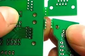
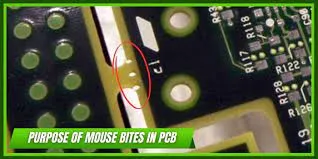
PCB mouse bites are small, perforated sections or breakaway tabs along the edges of a circuit board. They are designed to hold individual PCBs together in a panel during manufacturing and assembly, making it easier to handle multiple boards at once. Once the manufacturing process is complete, these mouse bites allow for easy separation of the boards by applying minimal force, often by hand or with simple tools.
These perforations look like tiny bite marks—hence the name "mouse bites." They are an alternative to other depaneling methods like V-scoring, where a groove is cut into the board to guide separation. Understanding the physics behind mouse bites is crucial for ensuring they don’t compromise the structural integrity of the PCB or introduce unnecessary stress points.
The Role of Mouse Bites in PCB Manufacturing
During PCB production, multiple boards are often fabricated on a single panel to save time and reduce costs. Mouse bites serve as temporary connectors that keep these boards attached during processes like soldering, testing, and assembly. Once these steps are complete, the boards need to be separated without damaging the delicate components or traces.
Mouse bites are strategically designed with small holes or perforations that reduce the amount of material connecting the boards. This makes separation easier while minimizing the risk of cracks or damage. However, the design of these perforations is not arbitrary—it’s deeply rooted in the principles of physics, particularly fracture mechanics and mechanical stress.
The Physics of Mouse Bites: Why They Matter
The science behind mouse bites, or mouse bites science, revolves around how materials behave under stress and how controlled fractures can be engineered into a design. Let’s break down the key physical concepts at play:
1. Mechanical Stress and Stress Concentration
Mechanical stress is the force per unit area that a material experiences when subjected to external loads, such as bending or twisting. In the context of PCBs, stress can occur during the separation process or even during normal operation if the board is exposed to vibrations or thermal expansion.
Mouse bites are intentional weak points in the PCB panel. While this makes separation easier, it also creates areas of stress concentration. According to engineering principles, stress concentration factors (SCF) at sharp edges or holes can increase local stress by 2 to 3 times compared to surrounding areas. If not designed properly, these stress points can lead to unintended cracks or damage during handling or operation. For instance, in high-vibration environments like automotive electronics, poorly designed mouse bites could cause the board to fail if the stress exceeds the material’s yield strength, often measured in megapascals (MPa) for common PCB substrates like FR-4, which typically has a tensile strength of around 310 MPa.
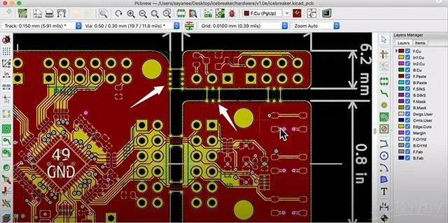
To mitigate this, designers must carefully plan the size, spacing, and shape of mouse bites. Typically, perforations are spaced 0.5 to 1 mm apart, with hole diameters of about 0.3 to 0.5 mm, to balance ease of separation with structural integrity.
2. Fracture Mechanics in PCB Separation
Fracture mechanics is the study of how cracks form and propagate in materials under stress. When you snap a PCB along its mouse bites, you’re initiating a controlled fracture. The perforations act as pre-defined crack initiation points, guiding the break along a specific path and preventing damage to critical areas of the board.
The success of this controlled fracture depends on the material properties of the PCB and the design of the mouse bites. If the perforations are too close together, the board may break prematurely during handling. If they’re too far apart, excessive force may be needed, risking damage to nearby components or traces. The goal is to achieve a clean break with minimal stress on the rest of the board, which requires a deep understanding of how cracks propagate through materials like fiberglass-reinforced epoxy (FR-4), the most common PCB substrate.
3. Material Properties of PCB Substrates
The choice of PCB materials plays a significant role in how mouse bites behave under stress. Most PCBs are made from FR-4, a composite material with a glass transition temperature (Tg) of around 130-140°C and a tensile strength of approximately 310 MPa, as mentioned earlier. FR-4 is relatively brittle, meaning it can fracture cleanly along mouse bites if designed correctly. However, excessive force or poor design can lead to jagged edges or microcracks that compromise the board’s reliability.
For specialized applications, materials like polyimide (used in flexible PCBs) or high-frequency laminates may be used. These materials have different mechanical properties, such as higher flexibility or lower tensile strength, which affect how mouse bites perform during separation. For instance, polyimide has a tensile strength of about 231 MPa, making it less prone to brittle fracture but potentially harder to separate cleanly without proper perforation design.
Designers must consider the material’s modulus of elasticity (a measure of stiffness, typically around 22 GPa for FR-4) and fracture toughness (the ability to resist crack propagation) when planning mouse bite placement. These properties determine how much force is needed to break the board and whether the separation will be smooth or cause unintended damage.
Designing Mouse Bites for Optimal Performance
Now that we understand the physics behind mouse bites, let’s explore how to design them effectively to minimize risks and ensure clean separation. Here are some practical tips for engineers:
- Perforation Size and Spacing: Use hole diameters of 0.3 to 0.5 mm and space them 0.5 to 1 mm apart. This balance ensures the board holds together during manufacturing but separates easily when needed.
- Edge Clearance: Keep mouse bites at least 2 mm away from sensitive components or traces to avoid damage during separation. This clearance helps reduce the risk of microcracks propagating into critical areas.
- Material Consideration: Match the mouse bite design to the PCB material. For brittle materials like FR-4, use more perforations to reduce the force needed for separation. For flexible materials, fewer but larger holes may be more effective.
- Stress Analysis: Use simulation tools to model mechanical stress around mouse bites. Finite Element Analysis (FEA) can help predict stress concentration factors and identify potential failure points before manufacturing.
Mouse Bites vs. V-Scoring: A Physics-Based Comparison
Mouse bites aren’t the only method for depaneling PCBs. V-scoring, where a V-shaped groove is cut into the board, is another common technique. Let’s compare the two from a physics perspective:
- Stress Distribution: Mouse bites create discrete stress concentration points at each perforation, while V-scoring creates a continuous line of stress along the groove. Mouse bites often require less force to separate (typically 10-20 N for a well-designed panel) compared to V-scoring (20-30 N), depending on the depth of the groove.
- Fracture Control: Mouse bites provide better control over the fracture path due to the perforations guiding the break. V-scoring can sometimes result in uneven breaks if the groove isn’t perfectly aligned or if the material has inconsistencies.
- Material Impact: V-scoring can weaken the board more than mouse bites, especially in thinner PCBs (below 1 mm), as it removes more material. Mouse bites preserve more of the board’s structural integrity, which is critical for applications with high mechanical stress.
Choosing between mouse bites and V-scoring often depends on the specific requirements of the project, including board thickness, material, and cost constraints. For most standard applications with FR-4 boards of 1.6 mm thickness, mouse bites offer a good balance of ease and reliability.
Challenges and Risks of Mouse Bites
While mouse bites are a practical solution for depaneling, they come with potential challenges that engineers must address:
- Crack Propagation: If not designed properly, the stress from breaking mouse bites can cause microcracks to spread into the board, potentially damaging traces or vias. This is especially problematic in high-density designs where components are placed close to the edge.
- Residue and Debris: Separating boards can leave rough edges or small debris at the mouse bite locations, which may interfere with assembly or cause short circuits if conductive particles are present.
- Thermal and Vibrational Stress: In environments with frequent temperature changes (e.g., -40°C to 85°C in automotive applications) or vibrations, mouse bite areas can become weak points, leading to premature failure if the local stress exceeds the material’s fatigue limit, often around 50% of its tensile strength for FR-4.
To minimize these risks, rigorous testing and simulation are essential during the design phase. Tools like thermal cycling tests and vibration analysis can help predict how mouse bites will hold up under real-world conditions.
Conclusion: Mastering Mouse Bites with Physics
Understanding the physics behind PCB mouse bites is more than just a theoretical exercise—it’s a critical step in designing reliable and efficient circuit boards. By considering mechanical stress, fracture mechanics, and the properties of PCB materials, engineers can optimize mouse bite designs to ensure clean separation without compromising the board’s integrity. The science of mouse bites science offers valuable insights into balancing manufacturing convenience with long-term reliability.
Whether you’re working on a prototype or a high-volume production run, paying attention to the small details of mouse bite design can make a big difference. With the right approach, you can minimize risks, reduce costs, and ensure your PCBs perform as intended in even the most demanding applications.