ALLPCB


Medical device OEMs are developing higher-functionality personal health devices for treating and monitoring common conditions. These devices can improve healthcare quality. MCUs play an important role in portable medical devices such as home blood pressure monitors, spirometers, pulse oximeters, and heart rate monitors. Most physiological signals in these products are analog and require amplification, filtering, and other front-end processing before measurement, monitoring, or display.
Embedding high-performance analog peripherals into ultra-low-power MCUs enables a single-chip approach for portable battery-powered medical devices and extends battery life. This article describes methods to simplify the analog front end for battery-powered portable medical devices, for example by combining operational amplifiers, ADCs, DACs, and other high-performance peripherals with a low-power MCU. The MCU provides digital filtering and processing and can display physiological parameters such as blood pressure, lung volume, heart rate, and blood oxygen saturation. Integrating these peripherals with the MCU supports all required functions and allows peripherals to be powered down to standby, meeting strict power budgets (currents on the order of a few mA).
The MSP430FG461x family is one example. Its 16-bit RISC CPU provides the required signal-processing capability while maintaining ultra-low operating current, enabling battery life of several years in these applications. The MCU integrates operational amplifiers, a 12-bit multichannel ADC, and dual 12-bit DACs as part of the analog signal chain. In addition to integrated analog peripherals, the device provides 120 KB of on-chip flash and a universal serial communication interface (USCI). The following sections describe how these integrated analog peripherals enable single-chip medical products.
Blood Pressure Monitor
Figure 1 shows a blood pressure monitor block diagram. These devices typically use a bridge-type pressure transducer connected to an inflatable cuff. The transducer can be enabled via a port pin and is only activated during pressure measurement to save power. The sensor output is on the millivolt scale and is proportional to pressure. That signal must be amplified before digitization by the ADC. The amplified signal is used to detect Korotkoff sounds and determine systolic and diastolic pressures.
Three on-chip operational amplifiers can be used to implement a high-gain differential amplifier that cancels common-mode noise. A differential amplifier block built from three op amps is shown in Figure 2. The amplified signal is routed internally to the 12-bit ADC. A DMA peripheral supports efficient data handling, enabling rapid execution of Korotkoff detection algorithms and filtering to remove measurement noise. The 16-bit CPU processes these algorithms at low MIPS. The device also integrates a 160-segment LCD driver with a regulated charge pump for stable contrast, further supporting the single-chip solution. The 120 KB low-power flash enables field firmware updates and, since the flash is system-programmable, it can also be used for data logging. The USCI serial port allows communication with a PC or PDA to download logged data. Because the MCU uses an ultra-low-power architecture, operating current in measurement mode is below 3 mA. In idle mode with the real-time clock and display active, current consumption is also under 3 mA.
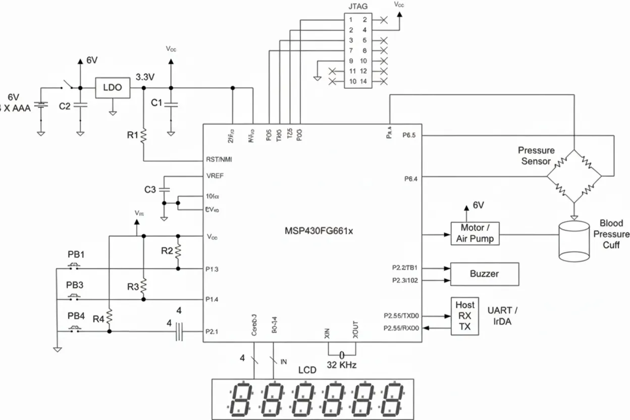
Pulse-width-modulated DC motor control handles cuff inflation and deflation. This is the only subsystem that requires a higher-voltage supply to drive the motor. If the motor cannot be driven from a single low-voltage source, the monitor can be powered by four low-cost AAA alkaline cells and a low-dropout regulator to provide 3.3 V for the MCU. Assuming two measurements per day, such batteries can last about two years. The MCU can remain in an active display timing mode for extended periods because that mode draws very little current. Viewing stored readings does not significantly increase current draw. The integrated dual-channel DAC can generate two sine waves 180 degrees out of phase to improve transducer performance.
Spirometer
A spirometer, or pulmonary function test (PFT) device, measures lung volume. In this application the measured parameter is flow over a fixed exhalation period, typically expressed in liters per minute. The sensor is a pneumatic transducer, effectively a differential pressure transducer. Aside from the absence of a motor, the spirometer design is similar to the blood pressure monitor. The three MCU operational amplifiers serve as the sensor amplifiers for the flow measurement. The remainder of the spirometer design is straightforward: the 12-bit ADC measures flow and compares it with stored normalized values. On-chip flash is useful for storing various normalization tables so the design can support different test conditions. Figure 1 can serve as a reference design for the spirometer because the transducers are similar. Note that the spirometer requires no motor control. The MCU's low-power characteristics extend battery life, and the high integration reduces system cost and improves reliability.
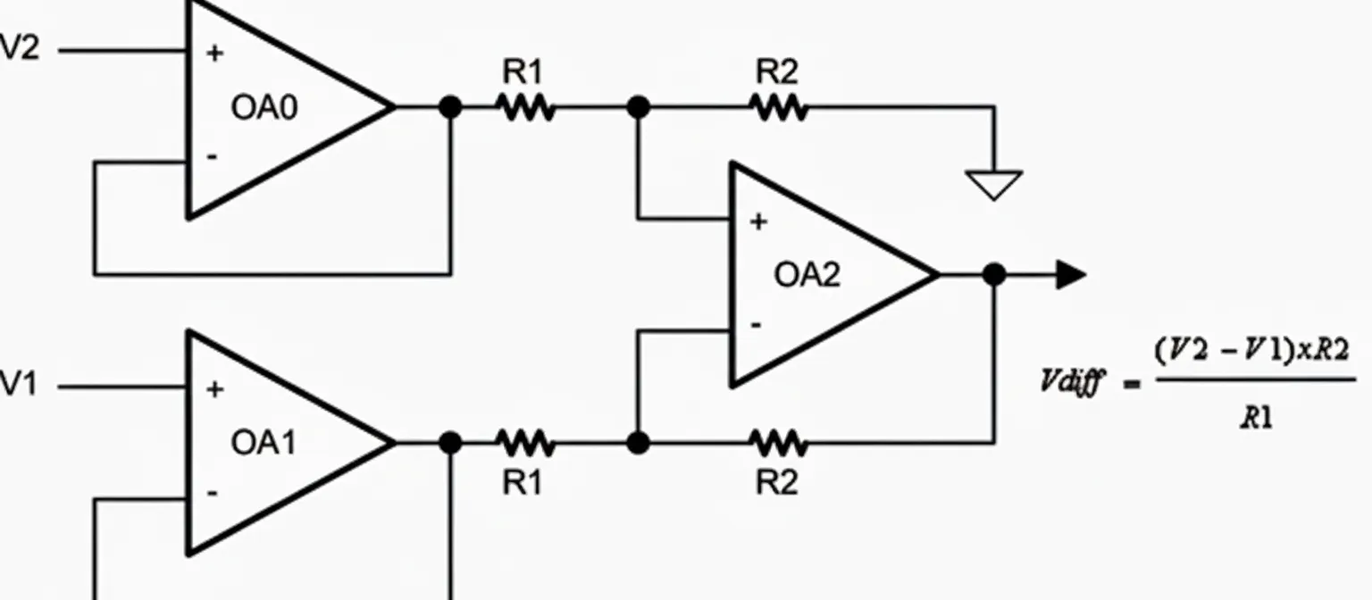
Figure 2 Differential amplifier
Pulse Oximeter and Heart Rate Monitor
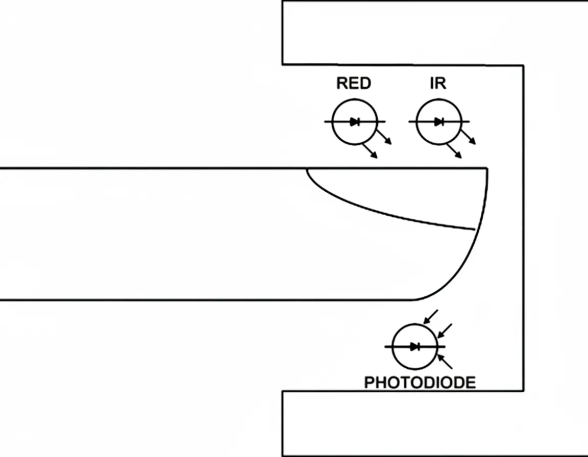
Several techniques exist for heart rate monitoring and pulse oximetry. This section focuses on noninvasive optical plethysmography. These pulse oximeters use an external probe with an MCU to display oxygen saturation and pulse rate. The same sensor can be used for both heart rate detection and SpO2 measurement. The method provides a simple and accurate estimate of arterial oxygen saturation and heart rate. The probe is placed on the fingertip, earlobe, or nose and contains two light-emitting diodes: one emitting visible red light (660 nm) and one emitting infrared light (940 nm). Light passes through tissue to a photodetector. Hemoglobin in red blood cells absorbs part of the light; absorption varies with oxygen saturation. By measuring absorption at the two wavelengths, the MCU calculates the proportion of oxygenated hemoglobin. The light transmitted through tissue also contains a pulsatile component caused by changes in arterial blood volume with each heartbeat.
Both LEDs must be driven by a constant-current source to maintain stable brightness during measurement. A constant-current source with automatic gain control (AGC) can be implemented using an internal DAC and simple MCU software. The MCU selects the pulsatile component of the detected light, while nonpulsatile venous blood, capillary blood, and other tissue pigments also absorb light. Modern measurement techniques reduce interference when calculating oxygen saturation. The two LEDs are typically switched on sequentially—red, then infrared, then both off—repeated several times per second. This time-division multiplexing removes background noise. A phase-quadrature multiplexing technique separates red and infrared signals by phase rather than time and then recombines them. This more advanced method can mitigate motion or electromagnetic interference because the recombined signals have phase differences.
Average blood oxygen saturation can be measured, and pulse rate is derived from the number of LED cycles between consecutive pulsatile signals. The time interval for computing the pulse rate average is roughly similar to the interval used to compute the saturation average, depending on the monitor implementation.
The ratio of the two wavelength absorptions is used to calculate both parameters. The MCU flash stores an experimentally derived lookup table of saturation values obtained from volunteers breathing gas mixtures with known oxygen concentrations. The MCU compares the measured ratio to the stored values and displays oxygen saturation as a percentage. Typical saturation readings range from 70% to 100%; values below 70% are estimates because experimental data for human subjects below 70% are limited.
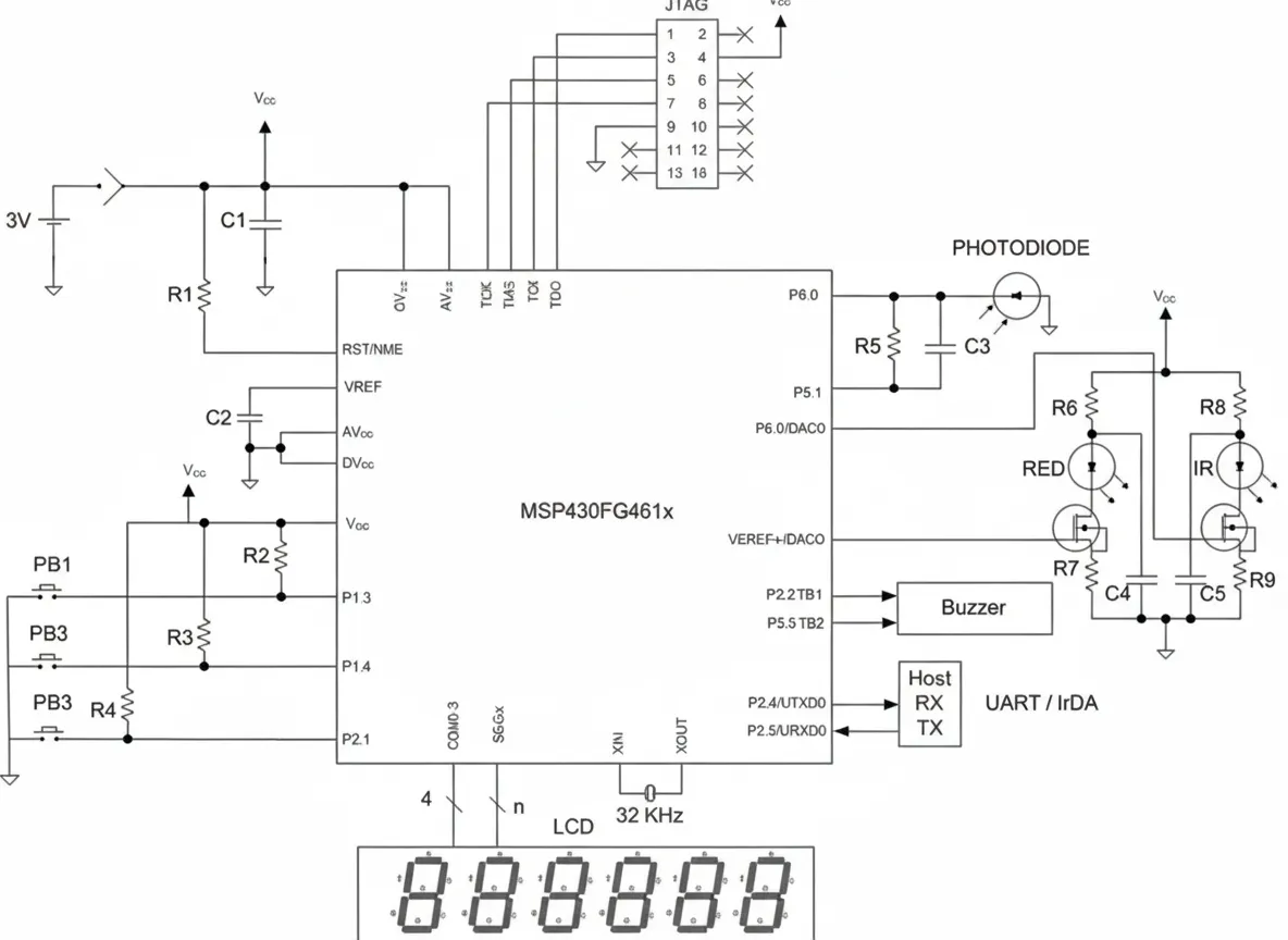
Figure 4 shows a pulse oximeter based on the MSP430FG461x. The application implements a complete analog front end including integrated operational amplifiers, ADC, and DAC. The DAC combined with the on-chip reference forms the constant-current source to drive the LEDs. One operational amplifier functions as the photodiode I/V transimpedance amplifier. LED brightness is adjusted using the DAC output and MCU software to implement AGC. The ADC digitizes the amplified and filtered detector output, and MCU software computes averages. This completes data acquisition and ratio calculation for red and infrared channels. The ratio is compared to stored calibration data to yield an accurate oxygen saturation value. The computed oxygen percentage is displayed on the LCD. The ADC samples also contain heart rate information; software can compute a heart rate average in about five seconds and display it on the LCD. A PWM output drives a piezo buzzer to produce a short beep on each heartbeat, providing feedback on sensor placement and signal quality.
Conclusion
In the portable medical applications described above, the ultra-low-power MCU MSP430FG461x functions as a single-chip solution with multiple advantages. The ADC accuracy easily meets measurement application requirements. On-chip operational amplifiers and DACs support signal conditioning and automatic gain control. After selecting a suitable MCU, the next step for system designers is software development. The MCU supports on-chip real-time emulation, allowing developers to perform real-time debugging via the JTAG port. A variety of compilers and debuggers are available, and debug hardware is inexpensive. The debugger hardware typically requires a simple logic-level translator to connect to a PC parallel port and does not require a traditional external ICE interface. Full-featured real-time emulation can set breakpoints in on-chip hardware, enabling full-speed execution during debugging. High integration and straightforward code development reduce system design cost. Flash can be reprogrammed during debugging to shorten development time, helping reduce time to market. The 120 KB of system-programmable flash can also be used for data logging.