ALLPCB


Overview
Body weight alone does not indicate health. Concern about body fat has driven demand for consumer body fat measuring devices.
An accurate method to determine body fat percentage is hydrostatic weighing: fully submerge the body, measure displaced volume, calculate body density from weight, and infer fat percentage. This method is impractical for routine use.
Principle
The human body contains roughly 70% water, most of which is in blood, lean tissue, and organs, while fat contains very little water. Body water, because it contains dissolved substances, has low resistance, whereas fat has high resistance. Therefore the ratio of fat to water affects the body's electrical resistance. Considering the combined resistance of fat and water, a body with more fat generally exhibits higher resistance. Most commercial body fat meters estimate fat content by measuring body impedance.
Device Concept
The following describes a simple, easy-to-build body fat meter.
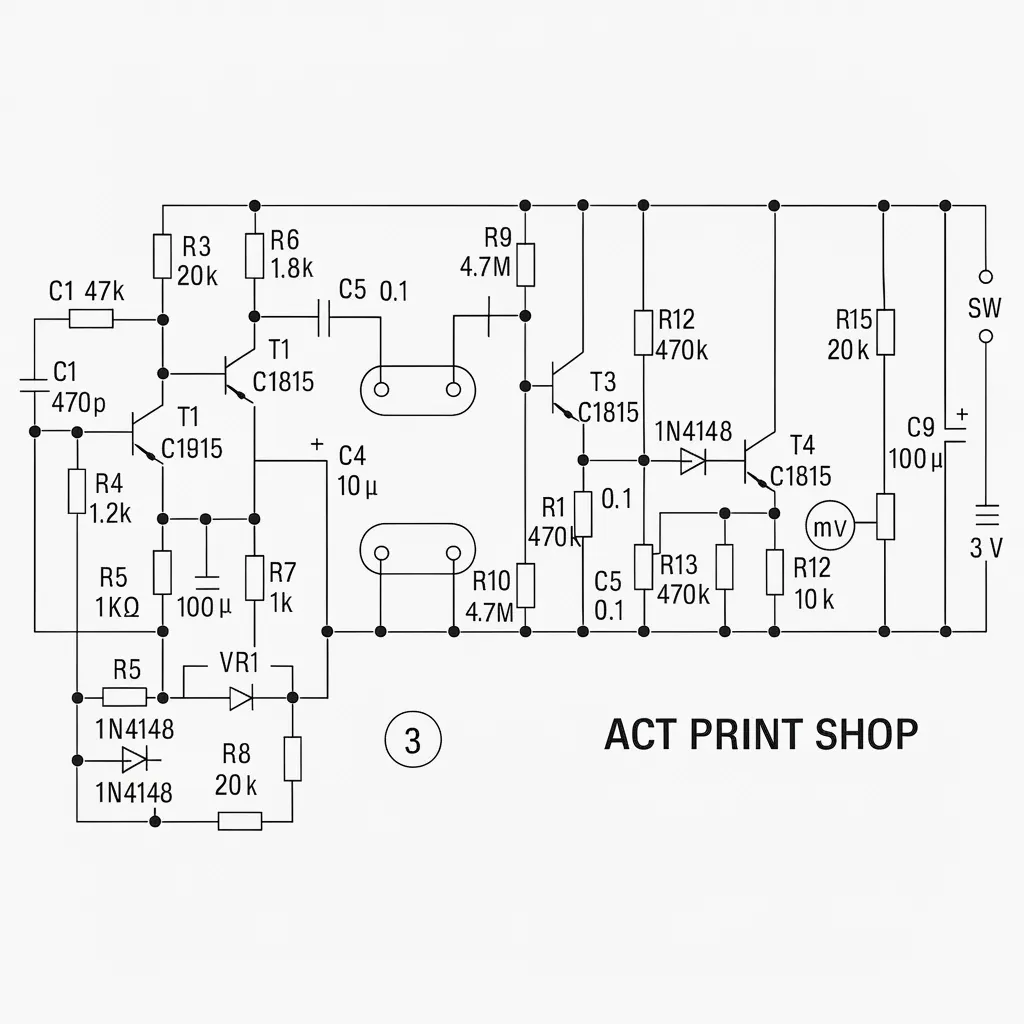
For simplicity, the signal source uses a 5 kHz sine wave. The design avoids a microcontroller and digital display. It is intended for monitoring changes in an individual user, so height and weight compensation are not included. Figure shows the complete circuit.
Circuit Description and Construction
T1 and T2 form a Wien-bridge oscillator that generates a 5 kHz sine wave. The output is coupled through C5 to one foot electrode; the other foot electrode is tied to the negative terminal of the power supply. The resistance between the two feet is therefore effectively in parallel with the signal source. Because typical foot-to-foot body resistance is on the order of hundreds of kiloohms, the detection input uses a high-input-impedance emitter follower T3.
The signal from T3 is rectified by a diode to extract a DC voltage related to body fat percentage, then buffered by an emitter follower T4 and presented to a voltmeter. Small input amplitude and the poor performance of conventional diode rectifiers for small signals are addressed by R12, which biases the diode so it conducts a small current even without signal. This improves sensitivity to small signals. To cancel the offset introduced by this bias, an adjustment network formed by R15 and VR2 provides zeroing. Because a digital voltmeter is used for measurement, no additional amplification stage is included after the detector. The entire circuit is powered by a 3 V battery.
Foot electrodes can be made from food-grade aluminum foil cut into four round pieces, two per foot. Use an insulating board similar in size to a commercial scale. At each foot position, attach double-sided tape sized to match the electrode. Thread stranded wires through holes from the underside and spread the wire ends over the tape surface, then press the electrode piece onto the tape so it contacts the wires firmly, forming a measuring pad.
Adjustment and Use
Verify the oscillator first. Use an audio cable to connect the C1 output and ground to a stereo amplifier. If the oscillator is functioning, an audible tone will be heard from a speaker. Adjust VR1 to vary the frequency.
Zero the detection circuit before use. Connect a digital multimeter on the mV range to the detector output. With the foot electrodes open-circuited, adjust VR2 until the meter reads 0 V. Then place a 1 M resistor between the two electrodes and press both palms on the upper and lower electrode plates; the meter should indicate about 10 to 20 mV.
For normal measurement, stand barefoot on the two electrode pads. The voltmeter will show a voltage, for example 9 mV, which can be used as a baseline for future comparisons. In general, higher voltage corresponds to higher fat content and lower voltage corresponds to lower fat content.