 ALLPCB


In the world of PCB assembly, a mixed technology component mounting approach combines the strengths of plated through hole (PTH) and surface mount technology (SMT) on the same board. This hybrid method allows engineers to leverage the durability of PTH components for high-power applications and the compact, efficient design of SMT for modern, high-density circuits. At ALLPCB, we understand the importance of this versatile technique in meeting diverse project needs. In this blog, we'll dive deep into what mixed technology entails, how it works, and why it’s a game-changer for many electronic designs.
What Is Mixed Technology in PCB Assembly?
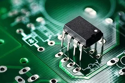
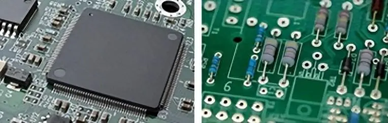
Mixed technology refers to a PCB assembly process that integrates both plated through hole and surface mount components on a single board. This approach is often used when a design requires the unique benefits of both technologies. PTH components, known for their strong mechanical bonds, are ideal for parts that endure physical stress or high currents, like connectors or large capacitors. On the other hand, SMT components are smaller, lighter, and perfect for high-density designs, such as microcontrollers or resistors in compact devices.
By combining these methods, mixed technology offers flexibility. It allows engineers to optimize space while ensuring reliability in demanding applications. This approach is common in industries like automotive, aerospace, and industrial electronics, where performance and durability are critical.
Understanding Plated Through Hole (PTH) Technology
Plated through hole technology involves drilling holes through a PCB and inserting component leads into these holes. The leads are then soldered to pads on the opposite side of the board, creating a strong mechanical and electrical connection. The "plated" aspect refers to the conductive copper lining inside the holes, which enhances connectivity between layers in multilayer boards.
PTH is often chosen for components that need to handle high power or mechanical stress. For example, a power supply connector might carry currents exceeding 10 amps, making PTH the preferred choice due to its robust connection. Additionally, PTH components are easier to replace or repair manually, which is beneficial for prototyping or maintenance.
However, PTH has limitations. It requires more board space because of the drilled holes and larger component sizes. This can be a drawback in designs where compactness is a priority. Also, the assembly process can be slower compared to SMT, as it often involves manual soldering or wave soldering techniques.
Exploring Surface Mount Technology (SMT)
Surface mount technology, in contrast, mounts components directly onto the surface of the PCB without drilling holes. These components, often much smaller than their PTH counterparts, are soldered to pads using reflow soldering—a process where solder paste is applied, components are placed, and the board is heated to melt the solder.
SMT is ideal for high-density designs. For instance, modern smartphones pack thousands of components into a tiny space, often using SMT parts as small as 0.4mm x 0.2mm (0402 package). This technology also supports faster, automated assembly, reducing production time and costs for large-scale manufacturing.
Despite its advantages, SMT has challenges. The smaller components can be less durable under mechanical stress, and repairs often require specialized equipment like hot air rework stations. Additionally, SMT may not be suitable for high-power applications where heat dissipation or current capacity is a concern.
Why Use a Mixed Technology Component Mounting Approach?
The mixed technology component mounting approach bridges the gap between PTH and SMT, offering the best of both worlds. Here are some key reasons why this method is widely adopted:
- Optimized Design Flexibility: Some designs require both high-power components and compact circuitry. For example, an industrial control board might use PTH for a power relay handling 15 amps and SMT for a microcontroller managing signals at 3.3 volts.
- Enhanced Reliability: PTH components provide durability for critical parts, while SMT allows for efficient use of space elsewhere on the board.
- Cost-Effective Solutions: Using SMT for smaller, less expensive components can reduce material costs, while PTH ensures reliability for high-value or critical parts.
- Adaptability to Legacy and Modern Designs: Mixed technology supports older components only available in PTH packages alongside newer SMT parts, ensuring compatibility in evolving designs.
This approach is particularly valuable in applications where boards must withstand harsh environments, like automotive electronics exposed to vibrations or temperature swings from -40°C to 85°C.
How Does Mixed Technology Assembly Work?
The assembly process for a mixed technology PCB typically involves multiple steps to accommodate both PTH and SMT components. Here's a simplified overview of how it’s done:
- Design and Layout: Engineers create a PCB layout that designates areas for PTH and SMT components. Software tools help ensure proper spacing and alignment, preventing interference between the two types.
- SMT Assembly First: SMT components are usually placed and soldered first using reflow soldering. Solder paste is applied to pads via a stencil, components are placed with precision pick-and-place machines, and the board is heated in a reflow oven to melt the solder. Typical reflow temperatures range from 240°C to 260°C for lead-free solder.
- PTH Assembly: After SMT components are secured, PTH components are inserted into pre-drilled holes. These are often soldered using wave soldering, where the board passes over a wave of molten solder at around 260°C, or by hand for low-volume production.
- Inspection and Testing: The assembled board undergoes visual inspection, automated optical inspection (AOI), and functional testing to ensure all components are correctly placed and soldered. For instance, impedance testing might confirm that signal traces maintain a target of 50 ohms for high-speed circuits.
At ALLPCB, we streamline this process with advanced equipment and rigorous quality control, ensuring that both PTH and SMT components are assembled with precision for reliable performance.
Challenges in Mixed Technology Assembly
While the mixed technology component mounting approach offers many benefits, it also comes with challenges that engineers must address:
- Thermal Stress: SMT and PTH components often require different soldering temperatures and methods. For example, reflow soldering for SMT might expose the board to 250°C, while wave soldering for PTH reaches 260°C. Multiple heat cycles can stress the board or components, potentially causing cracks or failures.
- Design Complexity: Balancing the placement of PTH and SMT components requires careful planning to avoid interference. PTH holes can limit routing options for SMT traces, especially in multilayer boards with high signal density.
- Assembly Time: Combining two assembly processes increases production time compared to using a single method. This can impact deadlines for high-volume orders.
- Cost Considerations: Mixed technology may raise costs due to the need for additional equipment, processes, and quality checks. For instance, wave soldering for PTH often requires specialized fixtures to protect SMT components already on the board.
Despite these hurdles, with proper design and manufacturing expertise, mixed technology remains a viable and often necessary solution for complex projects.
Role of Mounted Stencils in Mixed Technology Assembly
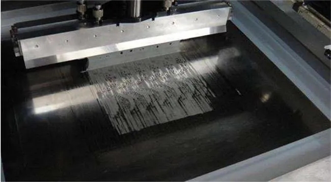
Mounted stencils play a crucial role in the SMT portion of mixed technology assembly. These stencils, typically made of stainless steel, are used to apply solder paste precisely to the PCB’s surface mount pads. The stencil is aligned over the board, and solder paste is spread across it, filling openings that correspond to the pads. This ensures that only the right amount of paste—often just 0.1mm to 0.15mm thick—is applied for each component.
In mixed technology boards, stencils must be designed to avoid areas where PTH components will be placed. This requires precise coordination between the stencil design and the PCB layout. A well-designed stencil minimizes issues like solder bridging or insufficient paste, which can lead to weak joints or assembly failures.
At ALLPCB, we use high-precision laser-cut stencils to ensure accurate solder paste application, even for fine-pitch SMT components as small as 0.5mm. This attention to detail is essential for the success of mixed technology assemblies.
Applications of Mixed Technology in Modern Electronics
The mixed technology approach is widely used across various industries due to its versatility. Here are some common applications:
- Automotive Systems: Control units in vehicles often combine PTH for power components like relays (handling up to 30 amps) and SMT for microcontrollers managing sensor data at 5 volts.
- Industrial Equipment: Machinery control boards use mixed technology to support heavy-duty connectors with PTH and compact logic circuits with SMT, ensuring reliability under vibration or heat.
- Medical Devices: Equipment like diagnostic machines may use PTH for stable power delivery components and SMT for densely packed processing chips, balancing performance and size.
- Consumer Electronics: Devices like power adapters integrate PTH for large capacitors handling 220V inputs and SMT for smaller control circuitry, optimizing space and safety.
This approach ensures that electronic products meet both performance and durability requirements, no matter the application.
Best Practices for Designing Mixed Technology PCBs
To achieve success with a mixed technology component mounting approach, engineers should follow these best practices during design and assembly:
- Plan Component Placement: Group SMT components together to streamline reflow soldering, and reserve accessible areas for PTH components to simplify wave soldering or manual insertion.
- Minimize Thermal Stress: Use components rated for multiple heat cycles, and design the assembly process to limit exposure to high temperatures. For instance, keep reflow cycles below 260°C if possible.
- Optimize Board Layout: Ensure PTH holes don’t interfere with SMT routing. Maintain clearances of at least 0.5mm between PTH holes and SMT pads to prevent solder flow issues.
- Choose Compatible Materials: Select PCB materials and components that can withstand the thermal and mechanical demands of mixed assembly. FR-4 boards, for example, are often suitable with a Tg (glass transition temperature) of 130°C to 140°C.
- Collaborate with Manufacturers: Work closely with your assembly partner to align design files, stencils, and soldering profiles for seamless integration of PTH and SMT processes.
At ALLPCB, we provide comprehensive support from design review to final assembly, ensuring that your mixed technology projects meet the highest standards.
Conclusion: The Power of Mixed Technology in PCB Assembly
The mixed technology component mounting approach, blending plated through hole and surface mount techniques, offers unparalleled flexibility for modern PCB designs. It allows engineers to balance durability, space efficiency, and performance, making it ideal for a wide range of applications—from automotive to medical electronics. While challenges like thermal stress and design complexity exist, proper planning and advanced manufacturing techniques can overcome them.
At ALLPCB, we’re committed to delivering high-quality mixed technology assemblies tailored to your specific needs. Whether you’re designing a compact consumer device or a rugged industrial system, our expertise in both PTH and SMT ensures your boards perform reliably. Explore our services to see how we can bring your next project to life with precision and efficiency.


